R5905948 /12 Event Master Devices 113
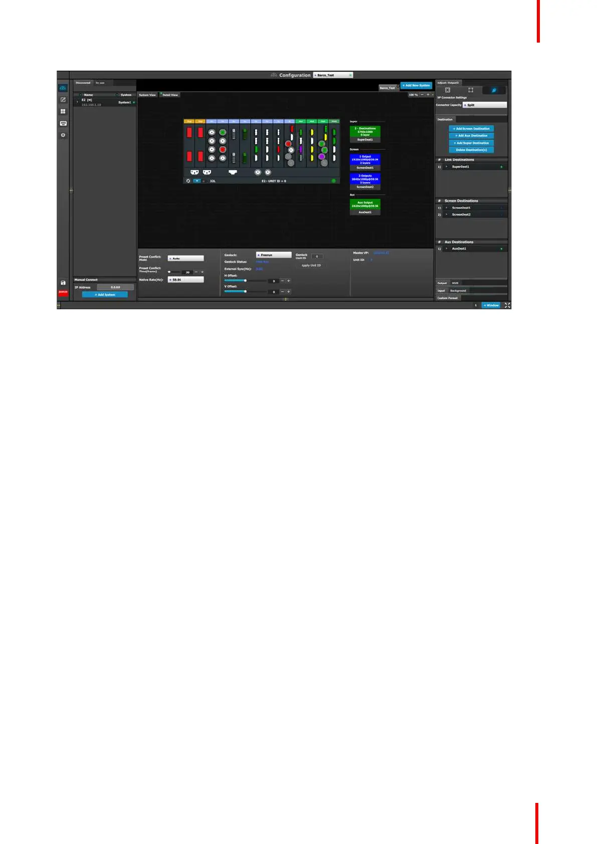
Image 6-9: Diagram area
In this area, the rear panel of the selected system is represented graphically with the cards, and the
connectors are color coded to indicate their status.
The color code is:
• White = Connector available to add and configure.
• Gray = Connector capacity set to NONE and is unavailable to add and configure.
• Purple = Connector capacity set to SPLIT; and connector is unavailable to add and configure.
Note: Any connector on a Gen 2 output card (HDMI 2.0 Quad Output, DP 1.2 Quad Output, or 4K Tri-
Combo Output card) may split to any other connector on the same Gen 2 output card. See Image 6-10.
• Red = Signal unavailable and connector configured into system.
• Yellow = Signal available.
• Green = Signal available and connector configured into system.
On the right hand side of the devices is a list of the created destinations (Screen and Auxiliary).
The tabs on the top allow access to the different systems connected to the EM GUI. The last tab allows the
users to add a new system.
A set of zoom buttons allows the user to reduce or enlarge the view size. This functionality is very useful when
the system is composed of more than one device.
EM GUI orientation