R5905948 /12 Event Master Devices186
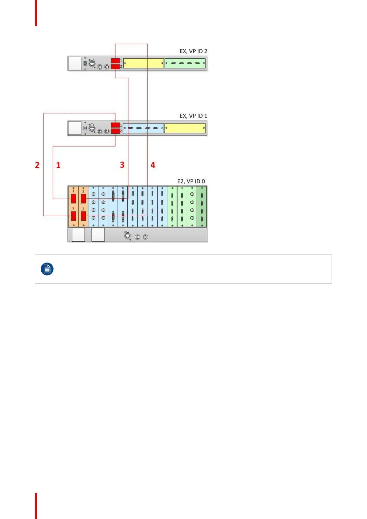
Image 6-51: Cabling between an E2 unit and two EX units, each with a VPU card
When an EX unit has VPU cards rather than a combination of Input and Output cards, and it is
connected to an E2 processor or to an S3–4K processor, the EX unit an no longer be daisy-chained
to another EX unit; both Link connectors on the EX unit must be connected to the E2 or S3–4K
Master unit.
Event Master Configuration for Linking an E2 Unit to Two EX Units with VPU Cards
1. Start the Event Master Toolset version 5.1 or higher.
2. Make sure that both the E2 and the EX are discovered on the network and that they have different Unit IDs.
3. Drop the E2 in the GUI.
If the E2 unit is cabled to an EX unit, the EX unit appears as a grayed-out box below the E2 unit in the Diagram
area. In the grayed-out EX box a blue button allows you to add the EX to the system as a slave.
4. Click the blue add button to add the EX unit.
5. (Optional) At this point it is suggested that you select and name appropriately each unit so that you can
identify it in your setup.
How to Link an E2 Unit and an S3–4K Unit
Each E2 comes equipped with two Link cards, always located in slots 1 and 2. Each S3–4K has a single Link
card in slot 1. Link cards are identified by a yellow stripe at the top. Make sure to use the locking mechanism
and then push each cable until it locks in place.
Connect the Link cables provided with each unit between the Link connectors as follows:
• E2 VP ID 0, Link Card slot 1, Link 1 >> S3–4K VP ID 1, Link Card slot 1, Link 2 [1]
• E2 VP ID 0, Link Card slot 1, Link 2 >> S3–4K VP ID 1, Link Card slot 1, Link 1 [2]
See Image 6-52 for an example of the cabling between an E2 unit and an S3–4K unit.
EM GUI orientation