R5905948 /12 Event Master Devices310
7. Type a new name, “PC-Background”. Press enter when done.
Image 9-6
In this application only one background is required, but in applications where more than one
background is required, repeat the appropriate steps above until done.
C3: Add Input
1. Click on the first SDI connector of slot 4 to be defined as the camera 1 input.
2. Click on the “Input” tab in the Adjustment pane to make the Input tab active.
3. Click on the +Add Single Input button to add that connector as an input for the system.
4. Double click on SDIInput2 in the Name list to edit the name.
5. When the area turns blue, click the eraser icon to clear the field.
6. Type a new name: “CAM1-Stage”. Press enter when done.
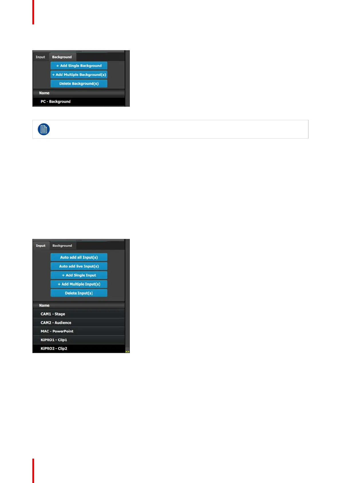
7. Repeat steps 1 thru 6 for the remaining connectors in Image 9-3. Enter the names as shown in the image
below.
Image 9-7
C4: Add Output
1. Click on the Output tab to make it active.
2. Click on the first HDMI connector of slot 11 to select it.
3. Click on the +Add Single Output button to add the output to the system.
4. Double click on HDMIOutput1 in the Name list to edit the name.
5. When the area turns blue, click the eraser icon to clear the field and type a new name, “DSM”. Press enter
when done.
General operation example