R5905948 /12 Event Master Devices550
DisplayPort connector
Pin
Signal
Pin
Signal
5 GND 15 AUX CH (p)
6 ML_Lane 1 (n) 16 GND
7 ML-Lane 2 (p) 17 AUX CH (n)
8 GND 18 Hot Plug Detect
9 ML_Lane 2 (n) 19 Return (return for power)
10 ML_Lane 3 (p) 20 DP_PWR Power for connector (3.3 V, 500
mA)
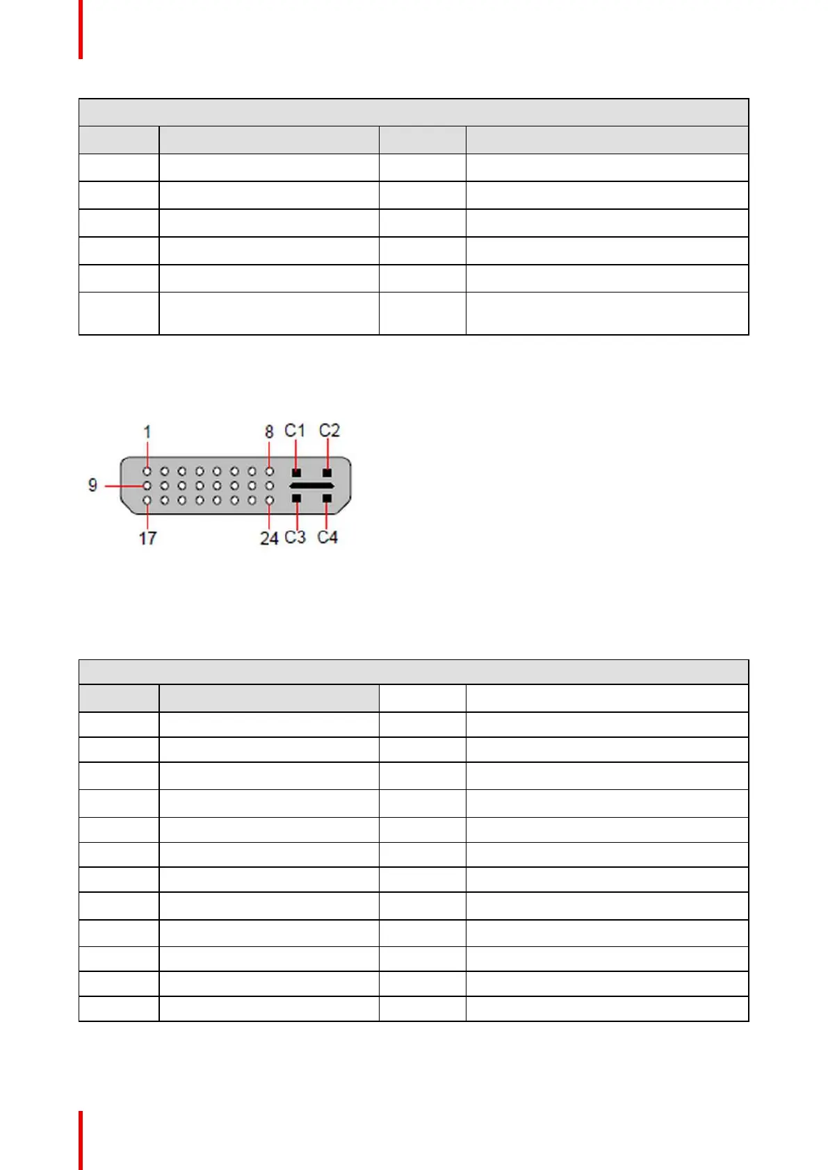
DVI connector pinouts
The following figure illustrates the DVI connector.
Image A-2: DVI connector
The following tables lists DVI Connector pinouts. Please note:
• T.M.D.S = Transition Minimized Differential Signal
• DDC = Display Data Channel
DVI connector
Pin
Signal
1 T.M.D.S. Data 2- 13 T.M.D.S. Data 3+
2 T.M.D.S. Data 2+ 14 +5V Power
3 T.M.D.S. Data 2/4 Shield 15 ground (for +5V)
4 T.M.D.S. Data 4- 16 Hot Plug Detect
5 T.M.D.S. Data 4+ 17 T.M.D.S. Data 0-
6 DDC Clock 18 T.M.D.S. Data 0+
7 DDC Data 19 T.M.D.S. Data 0/5 Shield
8 Analog Vertical Sync 20 T.M.D.S. Data 5-
9 T.M.D.S. Data 1- 21 T.M.D.S. Data 5+
10 T.M.D.S. Data 1+ 22 T.M.D.S. Clock Shield
11 T.M.D.S. Data 1/3 Shield 23 T.M.D.S. Clock +
12 T.M.D.S. Data 3- 24 T.M.D.S. Clock -
Specifications