Connectors
358 Manpack Transceiver 2110 series Reference Manual
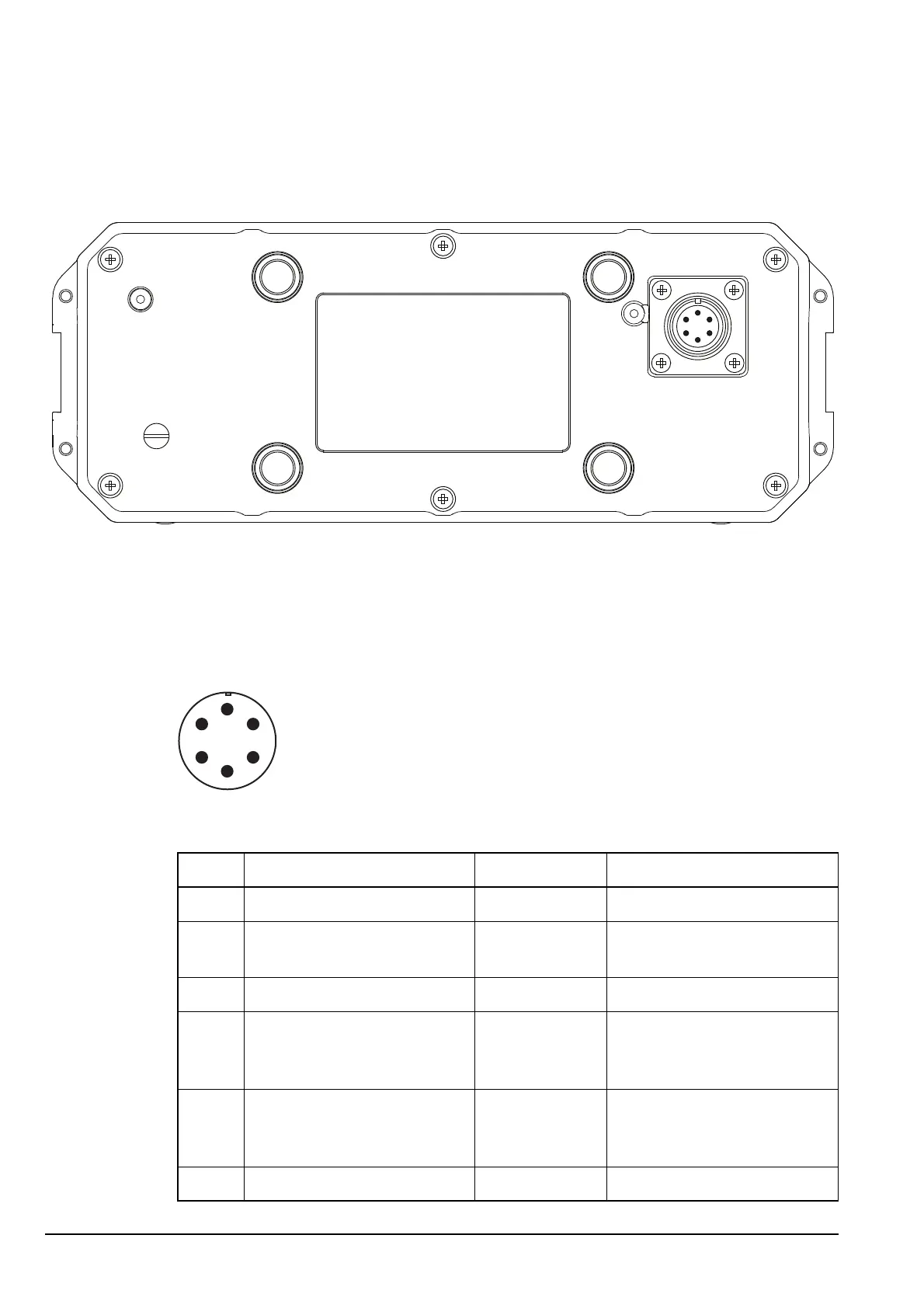
Back panel
Figure 59: Back panel of the transceiver unit
Pinouts of the battery connector on the transceiver unit
Figure 60: Front view of the battery connector on the transceiver unit
Table 47: Pinouts of the battery connector on the transceiver unit
Pin no. Function Input/output Signal level
A Ground 0 V DC
B Charge out Output 15.5 V DC @ 1 A maximum,
current limiting
C Battery+ Input 12 V DC nominal
D SMB data, or
SDA when external PA is
detected
Input/output 3.3 V DC logic
E SMB clock, or
SCL when external PA is
detected
Input/output 3.3 V DC logic
F External PA ALC Input 0 to 5 V DC analogue