A
B
C
D
E
F
G
H
L
M
N
P
section
P 6
78 1098/1098S - M.Y. 2007 - edition 00
Electric system
6 - Protection and safety devices
Checking protection and safety device components
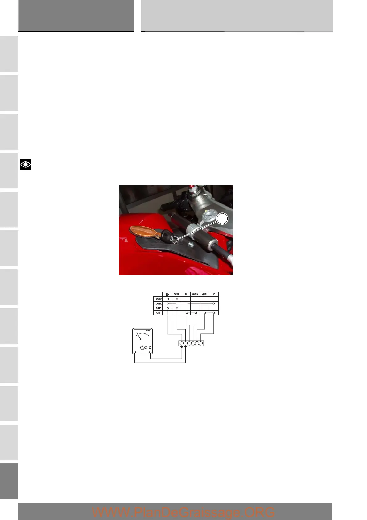
Checking the ignition switch
Disconnect the ignition switch (A) from the wiring loom by opening its connector (see “Routing of wiring on frame”, Sect. P 1)
and use a multimeter to check its internal connections as follows:
turn the key to OFF and connect a multimeter to contacts (1) and (4) to check electrical continuity (Sect. P 9, Diagnostic
instruments on operation of the multimeter). The resistance reading should be near zero and, if present, the continuity sound
signal should be emitted.
turn the key to ON and connect the multimeter to contacts (3) and (6) and then to (2) and (5) to check for electrical continuity.
The resistance reading should be near zero and, if present, the continuity sound signal should be emitted.
turn the key to PARK and connect the multimeter to contacts (1) and (4) and then to (3) and (5) to check for electrical continuity.
The resistance reading should be near zero and, if present, the continuity sound signal should be emitted.
turn the key to LOCK and connect the multimeter to contacts (1) and (4) to check for electrical continuity. The resistance reading
should be near zero and, if present, the continuity sound signal should be emitted.
Notes
The same check can also be performed using the “DDS” tester (Sect. D 5, DDS tester).
A
1
4
3
6
2
5
1