16
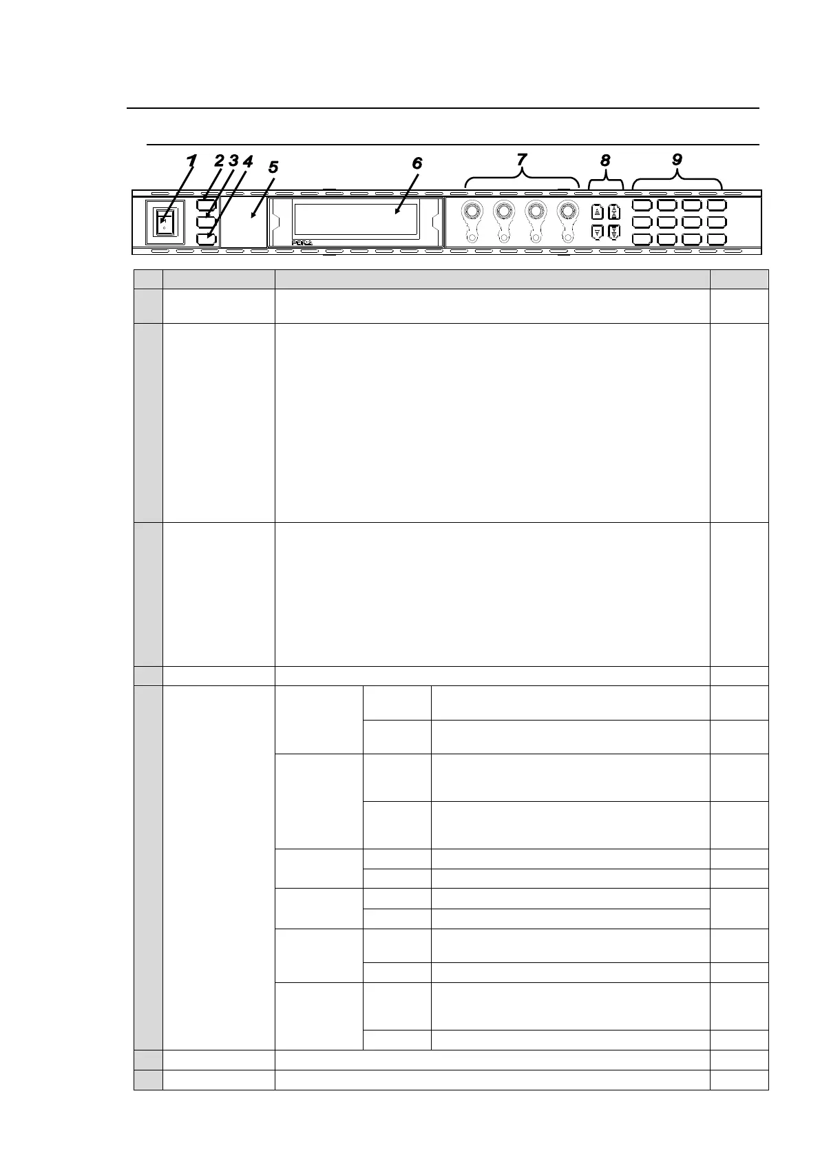
2. Panel Descriptions
2-1. Front Panel
Used to turn the unit ON / OFF. Pressing the "|" side turns on the
power.
LOCK button
(FA-9500 mode)
FS1/LOCK
(FA-9520 mode)
In FA-9500 mode:
Lit when pressed, and the buttons and controls on the front panel
except this LOCK button are disabled.
To enable the disabled buttons and controls, press and hold this button
down for several seconds.
In FA-9520 mode:
Used to select FS1 or FS2. There are linked menus that can be
changed simultaneously by pressing the FS1/LOCK and FS2/LOCK
buttons simultaneously. See 4-2-8 “2-channel frame synchronizer
switching” for details.
Disables operation only for FS1 when pressed and held down.
Press and hold this button down again to unlock operation.
* Both FS1 and FS2 LOCKs can be set simultaneously to disable all
other buttons except themselves.
In FA-9500 mode: Ineffective
In FA-9520 mode:
Used to select FS1 or FS2. There are linked menus that can be
changed simultaneously by pressing FS1/LOCK and FS2/LOCK
buttons simultaneously. See 4-2-8 “Switching Between 2-Channel
Frame Synchronizers” for details.
Disables operation only for FS2 when pressed and held down.
Press and hold this button down again to unlock operation.
* Both FS1 and FS2 LOCKs can be set simultaneously to disable all
other buttons except themselves.
Used to save and load events.
Input signal is present in FS1 or FS2.
No input signal is present in FS1 or FS2.
One or more assigned audio output signals
(FS1, FS2 embedded, AES and/or analog
audio) are present.
No assigned audio signal (FS1, FS2
embedded, AES and/or analog audio) is
present.
Genlock signal input is present.
No genlock signal input is present.
CONTROL SETTING is set to REMOTE.
CONTROL SETTING is set to LOCAL.
A power failure has occurred. Turn the power
of the unit OFF, and contact your supplier.
One or more fans have failed. Turn the power
of the unit OFF, and replace the failed fans if
needed.
All fans are operating normally.
Used to display menus and make operational settings
Used to change operational settings. Turn and select values.
MASTER
CONV2
OUT SEL
MODE
VIDEO
AUDIO
ANALOG
CONV1
IN SEL
DOWNMIX
STATUS
OTHER
C C
AES AUDIO
CLIP
DELAY
AUDIO SYS
VIDEO SYS
AUDIO OP
VIDEO OP
MAPPING
A V O
PROCESS
SDI AUDIO
F4
UNITYUNITYUNITYUNITY
F3
F2
F1
F A - 9 5 0 0
DISPLAY AREA
H D / S D F R AM E SYS NC HR ON I ZE R
VIDEO IN
AUDIO IN
GENLOCK
REMOTE
FAN ALARM
DC POWER
BY-PASS
LOCK
EVENT
ON
OFF
POWER
F1
F2
F3
F4