24
3-3. To Embed AES Input Signals on SDI Signals
The following describes how to embed 4 channel AES signals on SDI signals in SDI OUT 1 and
2 output signals
Settings that need to be checked:
Set FS1 IN SEL to SDI1 in the FS INPUT SELECT menu (see section 5-6-1).
Set SDI 1/2 to FS1 in the OUTPUT ASSIGN menu (see section 5-7-1).
Set CH1 through CH4 to AES CH1 through CH4, respectively, in the EMB1 OUT REMAP
menu (see section 6-5-1).
Change, if necessary, audio settings in the AES AUDIO Settings (AES AUDIO)
(section 6-2) and/or AUDIO DELAY Settings (section 6-6), and/ or the SRC mode
setting in the EMB1 SRC MODE menu (section 6-9-1).
AC100 - 240V 50/60 Hz I N 1
FAN2
SER. NO.
LAN2LAN1
REMOTE
DIGITAL AUDIO IN / OUT
7 / 85 / 63 / 41 / 2
ANALOG AUDIO
GENLOCK IN
COMPOSITE
OUT2OUT1IN
B
OUT4OUT3IN2OUT2OUT1
SDI
IN1
A
FAN1
AC100 - 240V 50/60 Hz IN2
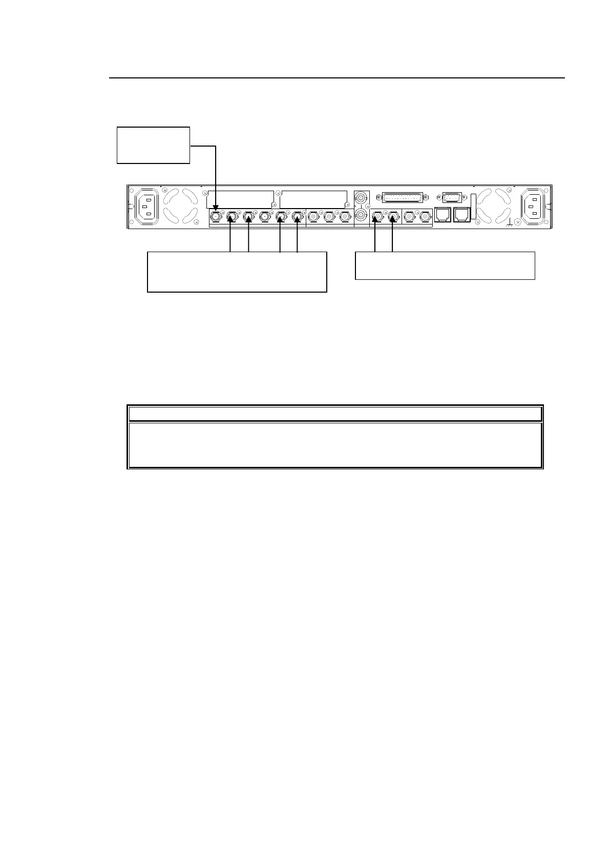
Input an HD/
SD-SDI signal
to SDI IN1.
Input AES signals to DIGITAL AUDIO IO
1/2, and IO3/4.
The AES signals are embedded to
AUDIO CH 1 through 4 of output signals
from SDI OUT1 and 2.