78
Conditions for by-passing SDI2 IN-SDI3 OUT circuit
The SDI2 IN to SDI3 OUT by-pass circuit is enabled, when FS1 input signal is assigned to
SDI2 and SDI 3/4 output is set to FS1, or, when FS2 input signal is assigned to SDI2 and SDI
3/4 output is set to FS2. If the BY-PASS setting cannot be turned ON, an “SDI2 BYPASS
DISABLED” message will be displayed.
Conditions for by-passing VBS IN-VBS OUT circuit
The VBS IN to VBS OUT by-pass circuit is enabled, when FS1 input signal is assigned to
COMPOSITE and COMPOSITE output is set to FS1, or, when FS2 input signal is assigned to
COMPOSITE and COMPOSITE output is set to FS2. If the BY-PASS setting cannot be turned
ON, a “VBS BYPASS DISABLED” message will be displayed.
See section 5-6-1 “FS INPUT SELECT” for details on FS1 and FS2 input signal assignments,
and 5-7-1 “OUTPUT ASSIGN” for details on output signal assignments.
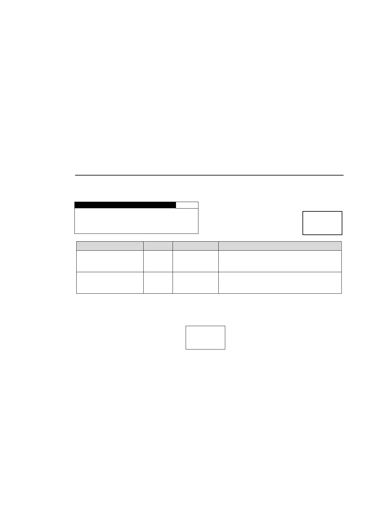
5-9-12. AIO BY-PASS SET
This setting is used to bypass through FA-95AIO input signals.
Input signals will be output to output connectors without being internally processed.
A I O O P A I N - O U T : O F F
A I O O P B I N - O U T : O F F
Setting to ON bypasses the input signal in
the FA-95AIO in option slot A to its output
connector with a relay connection.
Setting to ON bypasses the input signal in
the FA-95AIO in option slot B to its output
connector with a relay connection.
*1 Available only if the FA-95AIO is installed in option slot A.
*2 Available only if the FA-95AIO is installed in option slot B.
The AIO BY-PASS SET menu does not appear, if no FA-95AIO is installed in either option slot
A or B.
If any by-pass setting is set to ON: button flashes.
Conditions for by-passing AIO OP A IN-OUT circuit
The AIO OPT A IN-OUT by-pass circuit is enabled when the FS1 input signal is assigned to
OPTION A and AIO A ASSIGN output is set to FS1, or when the FS2 input signal is assigned
to OPTION A and the AIO A ASSIGN output is set to FS2. If AIO BY-PASS SET cannot be set
to ON, an “AIO OP A DISABLED” message will be displayed.
Conditions for by-passing AIO OP B IN-OUT circuit
The AIO OPT B IN-OUT by-pass circuit is enabled when the FS1 input signal is assigned to
OPTION B and AIO B ASSIGN output is set to FS1, or when the FS2 input signal is assigned
to OPTION B and the AIO B ASSIGN output is set to FS2. If AIO BY-PASS SET cannot be set
to ON, an “AIO OP B DISABLED” message will be displayed.