EasyManuals Logo

FOR-A FA-9520 User Manual

FOR-A FA-9520
280 pages
To Next Page IconTo Next Page
To Previous Page IconTo Previous Page
Page #239 background imageLoading...
Page #239 background image
239
14. REMOTE
14-1. REMOTE Connector
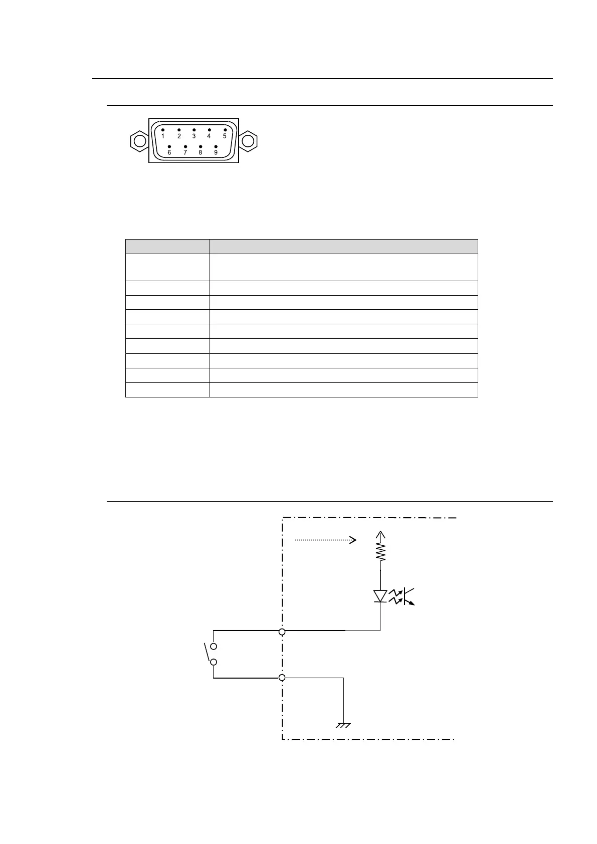
The pin assignments of the REMOTE (GPI) connector are as shown in the table below. The
connector has seven ports. Although the pin assignments below cannot be changed, the input
and output are selectable and the functions for GPI1 to GPI7 can also be selected.
REMOTE (GPI) Pin Assignments (9pin D-sub, male, inch screws)
Pin No.
Setting
1
DC OUT
(Up to 200mA output current is available at 5.4V.)
2
GPI 1 (input/output)
3
GPI 2 (input/output)
4
GPI 3 (input/output)
5
GPI 4 (input/output)
6
GPI 5 (input/output)
7
GPI 6 (input/output)
8
GPI 7 (input/output)
9
GND (ground)
See section 7-6. "GPI SETTING" for the function assignments for GPI1-GPI7.
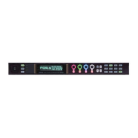
For GPI inputs, the function is ON when a pin is shorted to ground and OFF when open.
14-2. GPI Input Circuit
PIN 9
PINs 2-8
FA-9520 inside

Table of Contents

Other manuals for FOR-A FA-9520

Questions and Answers:

Question and Answer IconNeed help?

Do you have a question about the FOR-A FA-9520 and is the answer not in the manual?

FOR-A FA-9520 Specifications

General IconGeneral
BrandFOR-A
ModelFA-9520
CategorySignal Processors
LanguageEnglish

Related product manuals