243
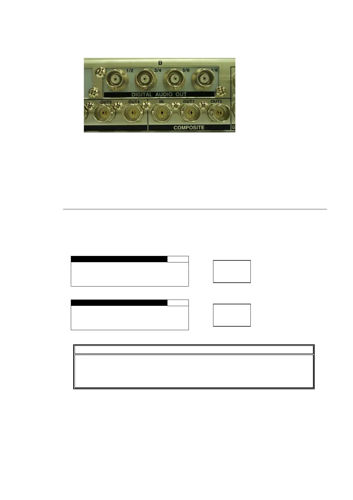
5. Install the BNC connector panel of the FA-95DACBL into the slot from inside the unit. Secure
the connector panel with the screws that were removed from the blank panel. (See the below
picture.)
6. If you have install the FA-95DACBL in slot A, set switch 5 in the S2 DIP switch to OFF.
If you have installed it into slot B, set switch 5 in the S2 DIP switch to ON.
7. Return and secure the top panel onto the unit with the 3 screws on top, and 4 screws each on
the right and left sides of the unit.
15-2. Installation Confirmation
Confirm the status of the FA-95DACBL on the front panel menu. See sections 7-9 “OPTION A
Ver.” and 7-10 “OPTION B Ver.”.
The menu appears as shown below, if the FA-95DACBL is installed;
in SLOT A
in SLOT B
N A M E : F A - 9 5 D A C B L
Four connectors of the FA-95DACBL digital audio expansion option can be used for
outputs. If the FA-95DACBL option is installed, the DIGITAL AUDIO IO connectors can
only be used for inputs and the AES I/O SETUP menu (section 6-2-4) is not
accessible.