18
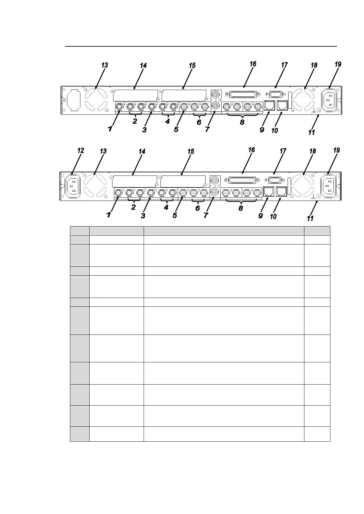
2-2. Rear Panel
FA-9520
FA-9520 with the FA-95PS option installed
Used for HD/SD-SDI video input 1.
Used for HD/SD-SDI video output 1.
The input signal in SDI IN 1 is output from SDI OUT1
when BY-PASS is enabled or the unit is turned off.
Used for HD/SD-SDI video input 2.
Used for HD/SD-SDI video output 2.
The input signal in SDI IN 2 is output from SDI OUT3
when BY-PASS is enabled or the unit is turned off.
Used for analog composite video input.
Used for analog composite video output.
The input signal in COMPOSITE IN is output from
COMPOSITE OUT1 when BY-PASS is enabled or the
unit is turned off.
Used for reference signal input (black burst or tri-level
sync) to synchronize the system. The bottom connector is
for a loop through. It must be terminated at 75 ohm when
not in use.
DIGITAL AUDIO
IO
1/2 - 7/8
Used for digital audio inputs and outputs. Select whether
to use for input or output as in section 6-2-4 “AES I/O
SETUP”.
A 1000/100BASE-TX/10BASE-T Ethernet LAN port.
Used to connect an external remote control unit or to
transfer data to an external device. RJ-45
A 1000/100BASE-TX/10BASE-T Ethernet LAN port.
Used to connect an external remote control unit or to
transfer data to an external device. RJ-45 (For future use)
Used to ground the unit to protect operators against static
electricity and electrical shock.
AC100 - 240V 50/60 Hz IN 1
FAN2
SER. NO.
LAN2LAN1
REMOTE
DIGITAL AUDIO IN / OUT
7 / 85 / 63 / 41 / 2
ANALOG AUDIO
G EN LO CK INCOMPOSITE
OUT2OUT1IN
B
OUT4OUT3IN2OUT2OUT1
SDI
IN1
A
FAN1
AC100 - 240V 50/60 Hz IN2
AC100 - 240V 50/60 Hz I N 1
FAN2
SER. NO.
LAN2LAN1
REMOTE
DIGITAL AUDIO IN / OUT
7 / 85 / 63 / 41 / 2
ANALOG AUDIO
GENLOCK IN
COMPOSITE
OUT2OUT1IN
B
OUT4OUT3IN2OUT2OUT1
SDI
IN1
A
FAN1
AC100 - 240V 50/60 Hz IN2