69
5-9. VIDEO SYSTEM (VIDEO SYS)
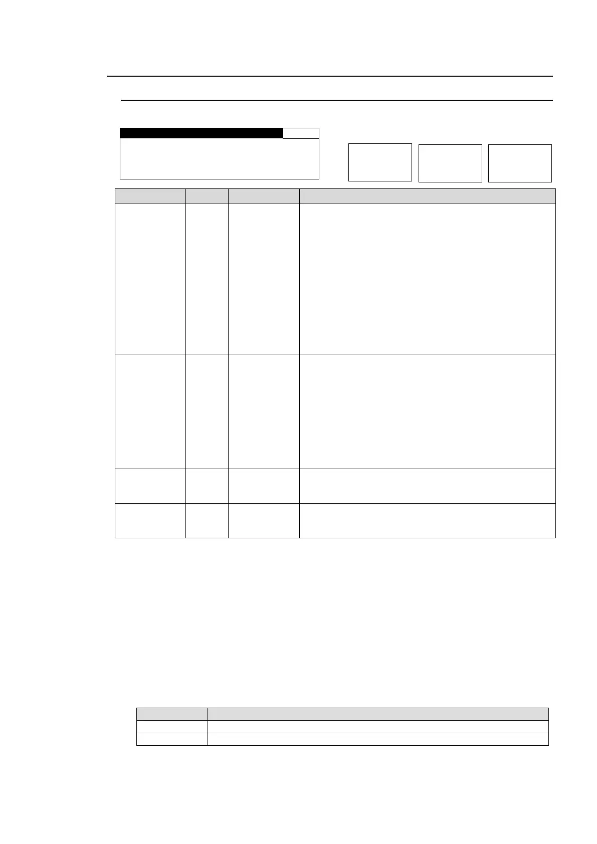
5-9-1. FS MODE SET
Allows you to set the FS (Frame Synchronizer) operation modes.
S Y N C H R O : F R A M E
SYNC F R M T : A U T O D E T
F R A M E D E L A Y : O F F
F O R C E D F I E L D : O F F
FRAME: Enables horizontal and vertical alignment of
video signals to a genlock signal. Effective on both
synchronous and asynchronous signals.
LINE: Locks the video signal of within ±1/2H to a
genlock signal. Output delay is 1H. Effective only when
video signal is synchronous to the genlock signal.
AVDL: Locks the video signal to a genlock signal with a
1H delay. Effective only when video signal is
synchronous to the genlock signal.
INPUT: Locks the system to an input video signal. The
delay can be adjusted by System Phase and/or Frame
Delay. However, the minimum delay is 520clk common
in all formats. (HD: 74MHz, SD: 27MHz) Does not use a
genlock signal.
AUTO DET
525/60
625/50
1080/59i
1080/50i
720/59p
720/50p
1080/23f
1080/24f
1080/59p
*2
1080/50p
*2
Sets a system format for the FA-9520.
AUTO DET: Detects and sets the detected input video
format to the system format.
Other values make the system work in the format.
Sets the amount of frame delay.
Selects which field to be used twice to compose a frame.
(Effective on composite signal inputs.)
* Settings can be set for FS1 and FS2, respectively.
*1 Selecting ODD/EVEN for FORCED FIELD, while IN SEL in section 5-6-1 “FS INPUT SELECT” is set to
COMPOSITE, SYNCHRO to FRAME, and FRAME DELAY is set to OFF, FRAME DELAY will always reset
to 1 frame. Set FRAME DELAY between 1 and 8 frames.
*2 FRAME DELAY cannot be set if SYNCHRO is set to LINE or AVDL. In such case, the menu will be
displayed as “FRAME DELAY: NOT ADJ”.
*3 FORCED FIELD cannot be set if SYNCHRO is set to LINE or AVDL. In such case, the menu will be
displayed as “FORCED FIELD: NOT ADJ”.
*4 The FREEZE function via GPI input is disabled if SYNCHRO is set to LINE or AVDL. See section 7-6 “GPI
SETTING” for details.
*5 Changing the SYNCHRO setting will reset V 1080 and V 720 settings in section 5-9-2 “HD PHASE SET”
and the V PHASE setting in section 5-9-3 “SD PHASE SET” to their default values according to the set
SYNCHRO mode.
*6 Switching input signals with a phase difference using a router or such device may cause shock noise to
occur on video or audio signals if the phase difference (compared to the genlock signal) exceeds the range
shown in the following table. If the difference is within range, shock noise will not occur.
Phase difference from genlock signal
-1H (with line differences depending on video format) to +1/2H
-5H (with line differences depending on video format) to +1/2H