173
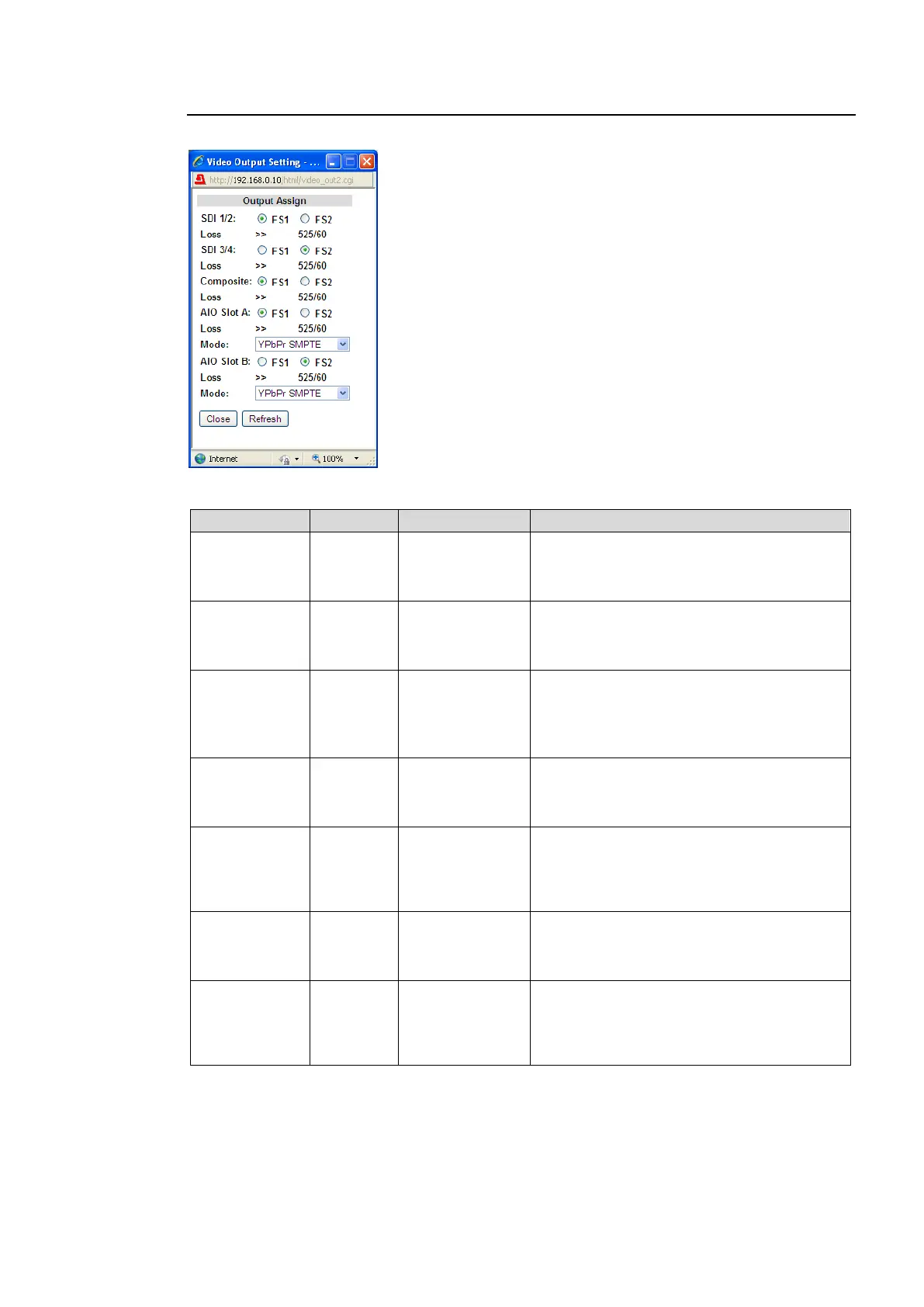
9-2-10. Output Assign
Clicking block (11) on the video block diagram opens the Video Output Setting dialog box.
Output Assign
Allows you to assign video signals to output from video output connectors.
Selects FS1 or FS2 of which signal to be
output from SDI1 and 2 connectors. I/O
formats of the selected FS are displayed
under the radio buttons.
Selects FS1 or FS2 of which signal to be
output from SDI3 and 4 connectors. I/O
formats of the selected FS are displayed
under the radio buttons.
Selects FS1 or FS2 of which signal to be
output from Composite connectors. I/O
formats of the selected FS are displayed
under the radio buttons.
Outputs a black signal for HD output signals.
Selects the signal to be output, FS1 or FS2,
from the FA-95AIO output connector in slot
A. I/O formats of the selected FS are
displayed under the radio buttons.
YPbPr SMPTE
YPbPr
BETACAM
RGB
Y/C
Selects the signal format for the FA-95AIO
video output in slot A.
Selects the signal to be output, FS1 or FS2,
from the FA-95AIO output connector in slot
B. I/O formats of the selected FS are
displayed under the radio buttons.
YPbPr SMPTE
YPbPr
BETACAM
RGB
Y/C
Selects the signal format for the FA-95AIO
video output in slot B.
*1 Shown only if the FA-95AIO is installed in option slot A.
*2 Shown only if the FA-95AIO is installed in option slot B.