190
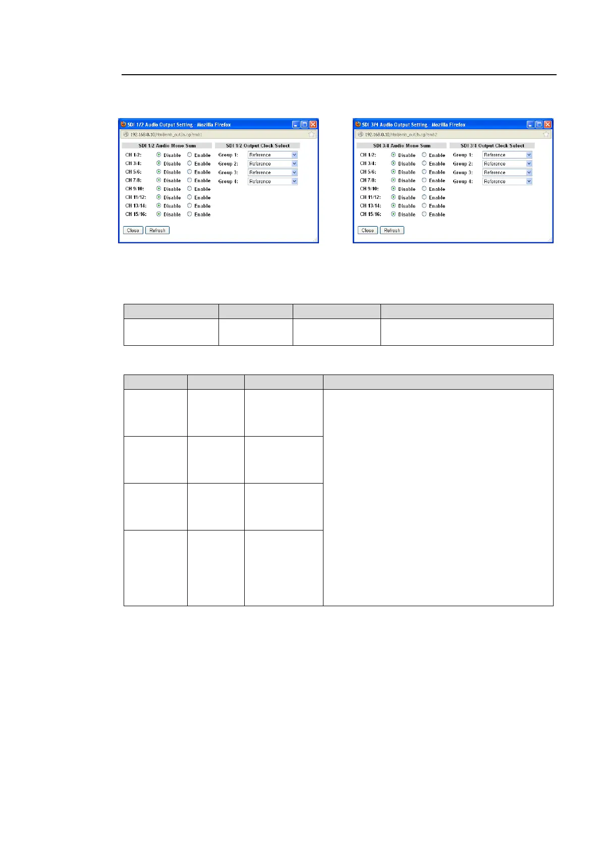
9-3-10. SDI Audio Output Settings
Clicking block (14) or (15) on the audio block diagram opens the SDI 1/2 or 3/4 Audio Output
Setting dialog box.
After completing the settings, click Close to close the dialog box.
Click Refresh to update the settings.
SDI1/2, 3/4 Audio Mono Sum
Enable: Outputs the stereo pair
channels as a mono sum.
SDI 1/2, 3/4 Output Clock Select
Auto
Reference
CH 1/2
CH 3/4
Selects an audio clock per group for SDI
embedded audio output.
Auto: Automatically selects audio clock input in
the NON-PCM signal channel, if an input
NON-PCM signal is in the selected SDI
embedded audio group. Automatically selects
audio clock signal in the smallest numbered
channel, if all signals in the audio group are
NON-PCM. Automatically selects audio clock
signal synchronized to the output video signal, if
all signals in the audio group are PCM.
*1
Reference: Audio clock synchronize with the
output video signal. (Used to synchronize audio
with the video signals processed in the SRC.)
CH 1/2 to 15/16: An input audio clock in channels
1/2 to 15/16.
To output asynchronous audio signals, select one
input channel pair for each group.
*1
For SD-SDI outputs, Reference is automatically
selected regardless of the setting.
Auto
Reference
CH 5/6
CH 7/8
Auto
Reference
CH 9/10
CH 11/12
Auto
Reference
CH 13/14
CH 15/16
*1 Embedded audio signals are divided into 4 groups. Each group consists of 4 audio
channels; Group 1 (CH 1 to 4), Group 2 (CH 5 to 8), Group 3 (CH 9 to 12), Group 4 (CH 13
to 16). The audio signals in the same group are transmitted together using the same audio
clock (48kHz). PCM audio signals will be synchronized to a genlock signal in the SRC
(sampling rate converter) so as to synchronize with the output video signal. Non-PCM audio
signals (compressed audio data such as AC-3) do not go into SRC. If the non-PCM audio
input signal is asynchronous with the output video signal, the non-PCM audio output signal
will be asynchronous. The asynchronous non-PCM audio signals can be embedded to SDI
video signals by selecting an audio clock for each audio group. To do so, all 4 channels in
the respective audio groups must be synchronous. Assign 4 synchronous audio signals to
channels in a group.