242
15. How to Install the FA-95DACBL
This section describes how to install the optional FA-95DACBL. If you have purchased the
FA-95DACBL with the FA-9520, this procedure is unnecessary since the FA-95DACBL has been
factory installed.
15-1. Procedure
1. Turn off the power of the FA-9520 and disconnect the power cord.
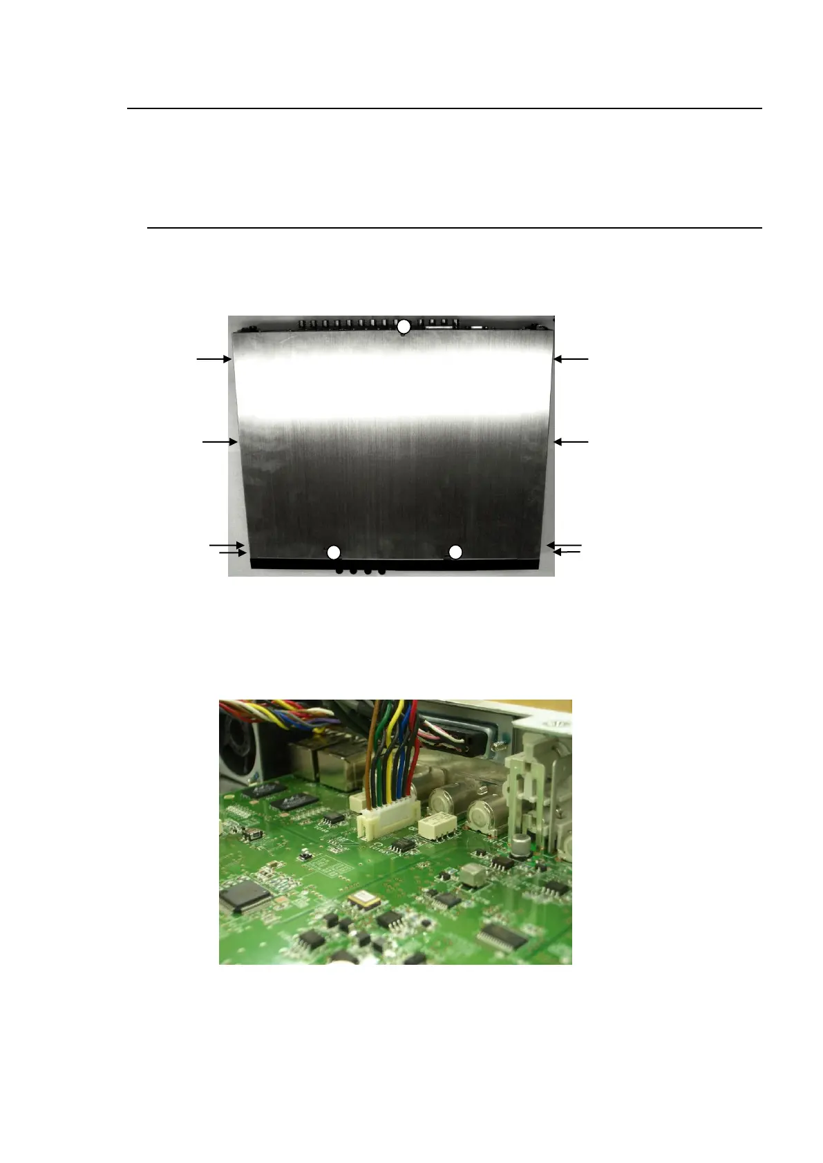
2. Remove the 3 screws from the top panel, and 4 screws each from the right and left sides of
the unit. Remove the top panel. (See the below picture.)
3. Remove the 2 screws from the blank panel on OPTION SLOT B. Keep these screws in a safe
place to use later to secure the FA-95DACBL. (To install the FA-95DACBL in slot A, remove
the screws from the blank panel on OPTION SLOT A.)
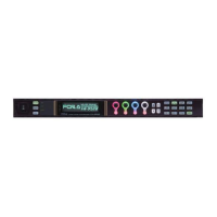
4. Connect the white connector of the FA-95DACBL to CN34. (See the below picture.)