19
Used to connect the unit to an AC power source.
(AC100V-240V 50/60Hz)
Enabled only when the optional redundant power unit
FA-95PS is installed.
The operation status can be viewed from the DC POWER
2 menu as described in section 5-10-1 “UNIT ALARM”.
(The menu is displayed if the optional FA-95PS is
installed.)
Used to air-cool the unit to prevent overheating. Do not
block the ventilation with other equipment or objects. The
operation status can be viewed from the FAN1 menu as
described in section 5-10-1 “UNIT ALARM”.
OPTION SLOT A for an optional expansion card.
OPTION SLOT B for an optional expansion card.
Used for four-channel analog audio input and output.
See section 12 “Analog Audio Connection” for details.
Used for remote control.
Assign functions to each pin.
See section 7-6 “GPI SETTING” for details on assigning
functions.
See section 14 “REMOTE” for connections.
Used to air-cool the unit to prevent overheating. Do not
block the ventilation with other equipment or objects. The
operation status can be viewed from the FAN2 menu as
described in section 5-10-1 “UNIT ALARM”.
Used to connect the unit to an AC power source.
(AC100V-240V 50/60Hz)
The operation status can be viewed from the DC POWER
1 menu as described in section 5-10-1 “UNIT ALARM”.
(The menu is displayed if the optional FA-95PS is
installed.)
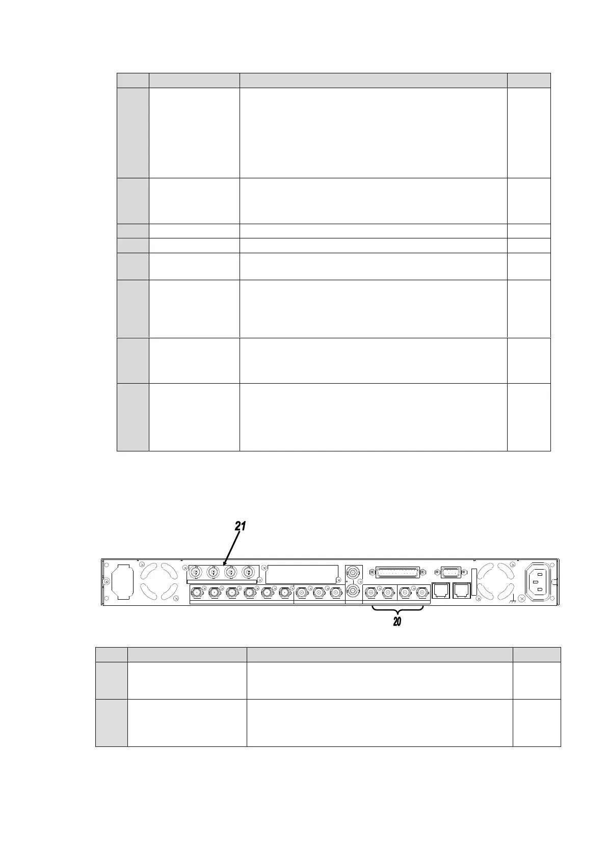
FA-9520 with the FA-95DACBL option installed
DIGITAL AUDIO IO
1/2 - 7/8
Digital audio input and output connectors.
Used only for inputs when the FA-95DACBL option is
installed.
DIGITAL AUDIO OUT
1/2 - 7/8
Digital audio output connectors. (FA-95DACBL option)
(The above figure of rear panel depicts an FA-95DACBL
option installed in slot A. The option can also be installed
in slot B.)
3/4 5/61/2 7/8
FAN2
3/4 7/8
FAN1
5/6
BA
COMPOSITE
1/2
LAN2
SDI
REMOTE
LAN1
COMPOSITE
OUT3OUT2IN1
SDI
ANALOG AUDIO
LAN2
DIGITAL AUDIO IN/OUT
OUT4OUT1 IN2 OUT1 OUT2IN
A
C
100-240V 50/60H
z IN
2
DIGITAL AUDIO OUT
S
E
R
.
N
O
.
GENLOCK IN
AC100-240V 50/60Hz IN 1