2.6.6.5. Transceiver Clocking and Channel Placement Guidelines in XAUI
Configuration
Transceiver Clocking
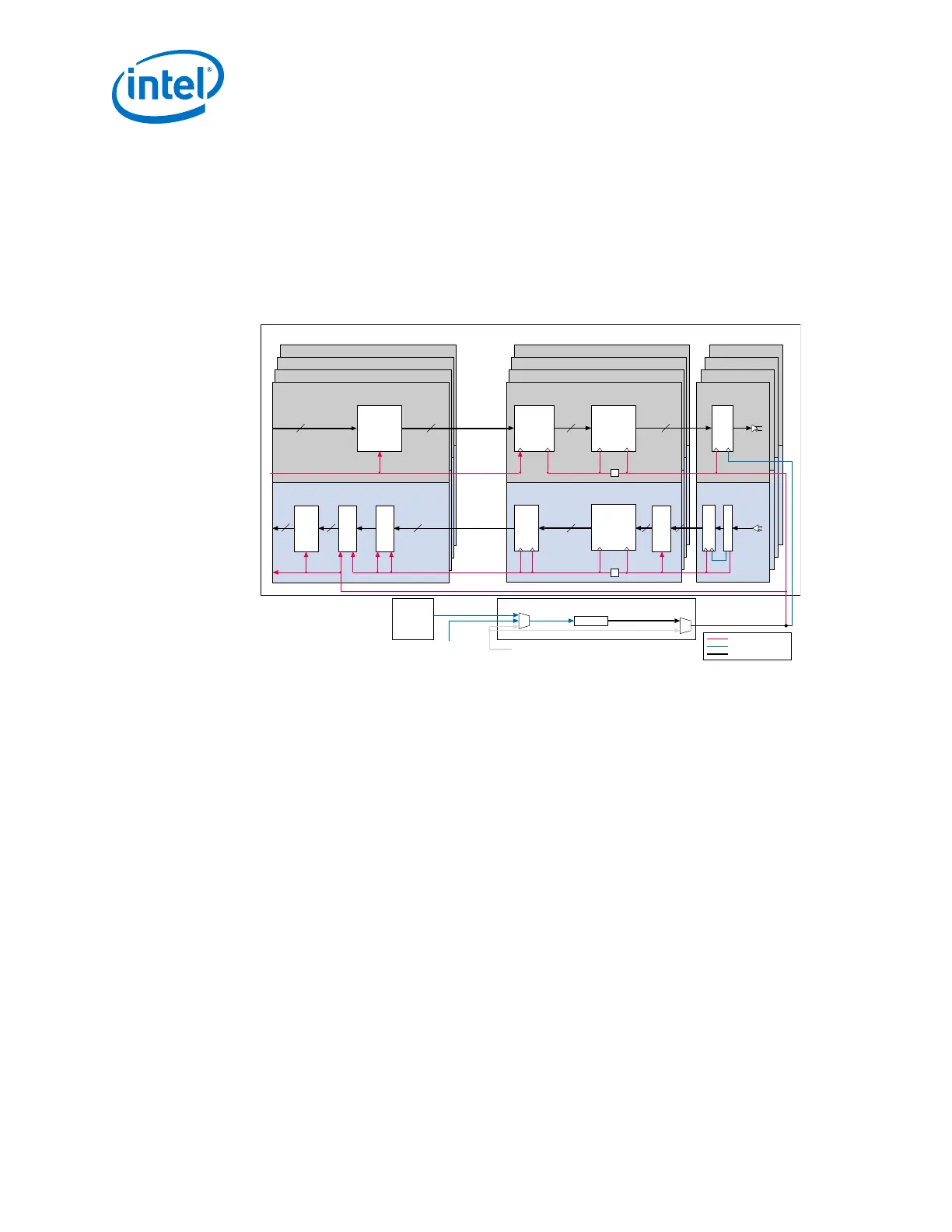
Figure 85. Transceiver Clocking for XAUI Configuration Without Phase Compensation
FIFO Enabled
The external ATX PLL generates the transmitter serial and parallel clocks for the four XAUI channels. You must
instantiate the PLL and connect it to XAUI. The x6 clock line carries the transmitter serial and parallel clocks to
the PMA and PCS of each of the four channels.
RX Phase
Compensation
FIFO
TX Phase
Compensation
FIFO
Byte Serializer
Receiver Standard PCS Receiver PMA
Deserializer
CDR
Transmitter Standard PCS
Transmitter Standard PCS
Transmitter Standard PCS
Transmitter Standard PCS
Channel 0
Channel 1
Channel 2
Channel 3
Transmitter PMA Ch 0
Transmitter PMA Ch 1
Transmitter PMA Ch 2
Transmitter PMA Ch 3
Serializer
tx_serial_data
rx_serial_data
Parallel Clock
Parallel Clock (Recovered)
Byte Deserializer
8B/10B
Decoder
Rate Match FIFO
Deskew FIFO
Word Aligner
8B/10B Encoder
Soft PCS
Soft PCS
Soft PCS
Soft PCS
XAUI PHY IP Core
Channel 3
Channel 2
Channel 1
Channel 0
16
16
20
20
20
2020
10
1010
xgmii_tx_clk
xgmii_rx_clk
/2
Parallel Clock
(Recovered) from Channel 0
Parallel Clock
/2
Clock Divider
Parallel and Serial Clocks (From the ×6 or ×N Clock Lines)
Serial Clock
(From the ×1 Clock Lines)
Master Clock Generation Block
Parallel Clock
Serial Clock
Parallel and Serial Clocks
(1)
ATX PLL
Note:
1. Use the ATX PLL as the transmit PLL for XAUI support in Arria 10 devices.
Note: When configuring ATX PLL, the PMA width setting must be set to 20-bit per transceiver
channel. This ensures that the serial clock is running at 3.125 Gbps while the input
reference clock is 156.25 MHz.
2. Implementing Protocols in Arria 10 Transceivers
UG-01143 | 2018.06.15
Intel
®
Arria
®
10 Transceiver PHY User Guide
220