• Using PLLs and Clock Networks on page 398
Information on how to use PLL IP to implement bonded and non-bonded
transceiver designs.
3.1. PLLs
Table 228. Transmit PLLs in Arria 10 Devices
PLL Type Characteristics
Advanced Transmit (ATX) PLL • Best jitter performance
• LC tank based voltage controlled oscillator (VCO)
• Supports fractional synthesis mode (in cascade mode
only)
• Used for both bonded and non-bonded channel
configurations
Fractional PLL (fPLL) • Ring oscillator based VCO
• Supports fractional synthesis mode
• Used for both bonded and non-bonded channel
configurations
Clock Multiplier Unit (CMU) PLL or Channel PLL
(50)
• Ring oscillator based VCO
• Used as an additional clock source for non-bonded
applications
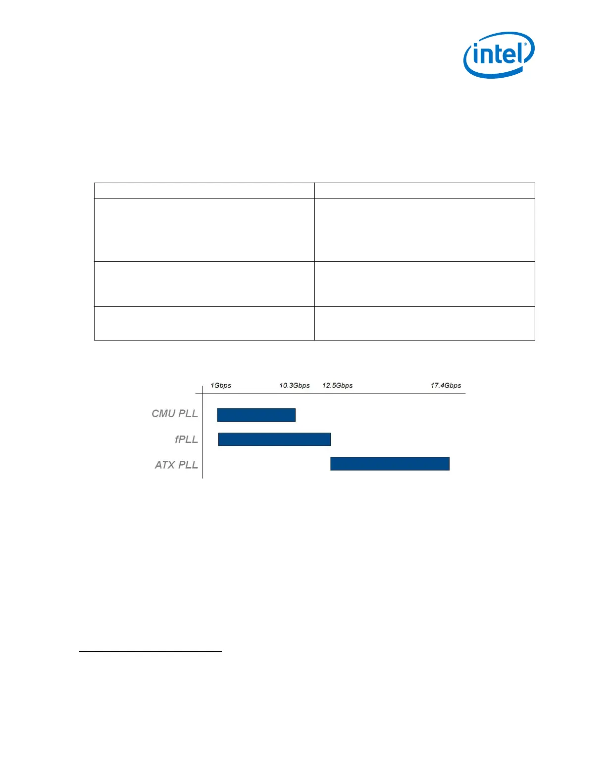
Figure 169. Transmit PLL Recommendation Based on Data Rates
Related Information
Refer to Using PLL and Clock Networks section for guidelines and usage on page 398
3.1.1. Transmit PLLs Spacing Guideline when using ATX PLLs and fPLLs
ATX PLL-to-ATX PLL Spacing Guidelines
For ATX PLL VCO frequencies between 7.2 GHz and 11.4 GHz, when two ATX PLLs
operate at the same VCO frequency (within 100 MHz), they must be placed 7 ATX PLLs
apart (skip 6).
(50)
The CMU PLL or Channel PLL of channel 1 and channel 4 can be used as a transmit PLL or as a
clock data recovery (CDR) block. The channel PLL of all other channels (0, 2, 3, and 5) can
only be used as a CDR.
3. PLLs and Clock Networks
UG-01143 | 2018.06.15
Intel
®
Arria
®
10 Transceiver PHY User Guide
349