KR FEC TX Gearbox
The KR FEC TX gearbox converts 65-bit input words to 64-bit output words to
interface the KR FEC encoder with the PMA. This gearbox is different from the TX
gearbox used in the Enhanced PCS. The KR FEC TX gearbox aligns with the FEC block.
Because the encoder output (also the scrambler output) has its unique word size
pattern, the gearbox is specially designed to handle that pattern.
5.2.2. Receiver Datapath
5.2.2.1. RX Gearbox, RX Bitslip, and Polarity Inversion
The RX gearbox adapts the PMA data width to the larger bus width of the PCS channel
(Gearbox Expansion). It supports different ratios (PCS-PMA interface width : FPGA
fabric–PCS interface width) such as 32:66, 40:66, 32:67, 32:64, 40:40, 32:32, 64:64,
67:64, and 66:64 and a bit slipping feature.
RX bitslip is engaged when the RX block synchronizer or rx_bitslip is enabled to
shift the word boundary. On the rising edge of the bitslip signal of the RX block
synchronizer or rx_bitslip from the FPGA fabric, the word boundary is shifted by
one serial bit or 1UI. Each bit slip removes the earliest received bit from the received
data.
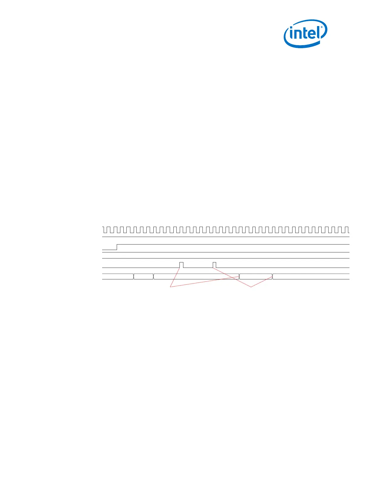
Figure 245. RX Bitslip
rx_bitslip is toggled two times, which shifts the rx_parallel_data boundary two bits.
00000001
00000000 00100000 00200000 00400000
tx_parallel_data (hex)
rx_parallel_data (hex)
tx_ready
rx_ready
rx_clkout
rx_bitslip
The second rising edge of rx_bitslip
makes another serial bit slip.
The first rising edge of
rx_bitslip makes 1 serial bit
The receiver gearbox can invert the polarity of the incoming data. This is useful if the
receiver signals are reversed on the board or backplane layout. Enable polarity
inversion through the Native PHY IP Parameter Editor.
Data valid generation logic is essential for gearbox operation. Each block of data is
accompanied by rx_enh_data_valid data valid signal which “qualifies” the block as
valid or not. The data valid toggling pattern is dependent on the data width conversion
ratio. For example, if the ratio is 66:40, the data valid signal is high in 20 out of 33
cycles or approximately 2 out of 3 cycles and the pattern repeats every 33
rx_clkout RX low-speed parallel clock cycles.
Note: If a design is slipping more bits than the PCS/PMA width, the Enhanced RX PCS FIFO
could overflow. To clear the overflow, assert rx_digitalreset.
5. Arria 10 Transceiver PHY Architecture
UG-01143 | 2018.06.15
Intel
®
Arria
®
10 Transceiver PHY User Guide
471