5. Instantiate and configure your PLL.
6. Create a transceiver reset controller. You can use your own controller or use the
Transceiver PHY Reset Controller.
7. Connect the Native PHY IP to the PLL IP and the reset controller.
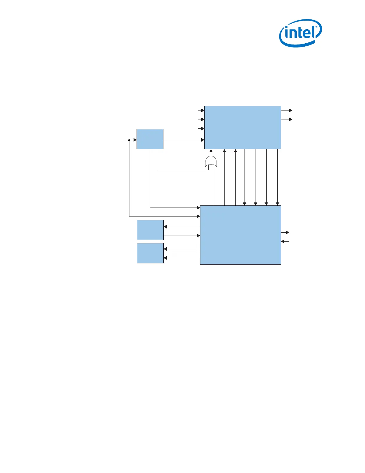
Figure 164. Connection Guidelines for a PCS Direct PHY Design
PLL IP Core
Data
Generator
Data
Verifier
Arria 10 Transceiver Native PHY
Reset Controller
rx_cdr_refclk
tx_serialclk0
pll_locked
pll_sel
reset
clk
pll_refclk
tx_ready
rx_ready
tx_parallel_data
tx_clkout
rx_parallel_data
rx_clkout
tx_serial_data
rx_serial_data
rx_is_lockedtodata
rx_cal_busy
tx_cal_busy
tx_analogreset
tx_digitalreset
rx_analogreset
rx_digitalreset
pll_cal_busy
8. Simulate your design to verify its functionality.
2.10. Simulating the Transceiver Native PHY IP Core
Use simulation to verify the Native PHY transceiver functionality. The Quartus Prime
software supports register transfer level (RTL) and gate-level simulation in both
ModelSim - Intel FPGA Edition and third-party simulators. You run simulations using
your Quartus Prime project files.
2. Implementing Protocols in Arria 10 Transceivers
UG-01143 | 2018.06.15
Intel
®
Arria
®
10 Transceiver PHY User Guide
325