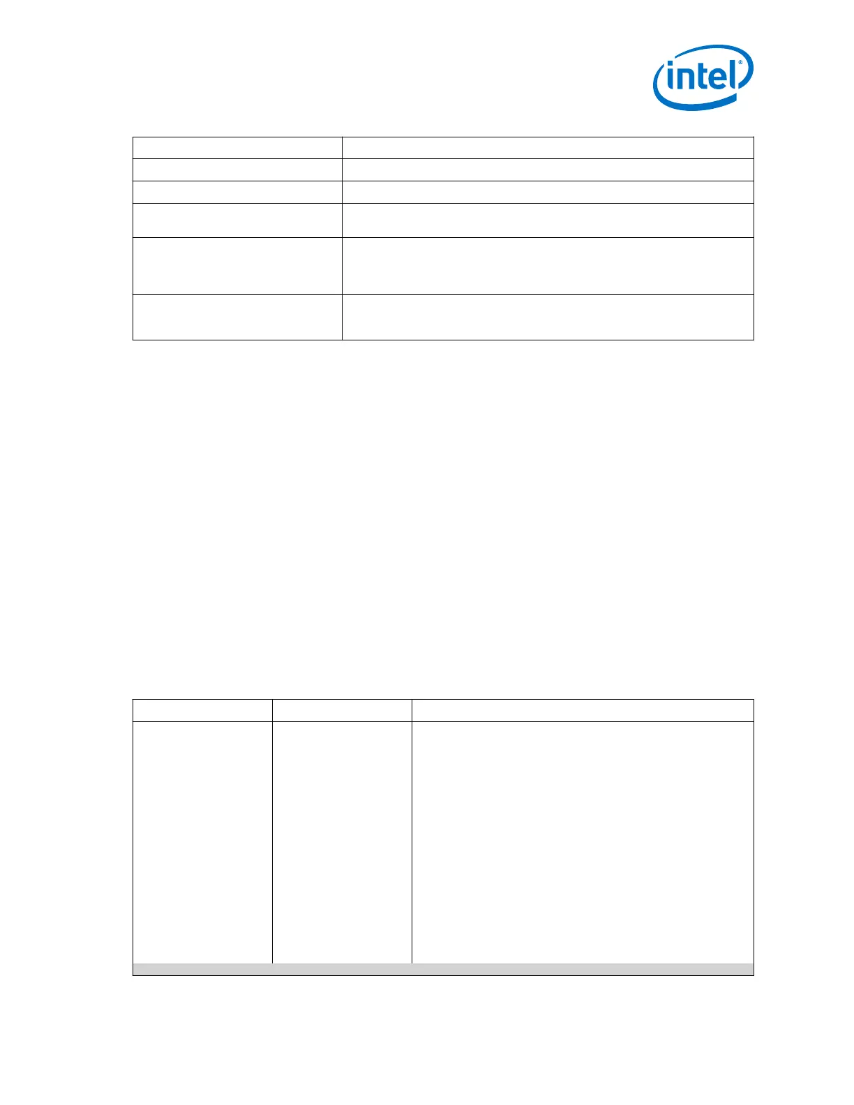
Transceiver Configuration Setting Description
10GBASE-R 1588 Enforces rules required by the 10GBASE-R protocol with 1588 enabled.
10GBASE-R w/KR FEC Enforces rules required by the 10GBASE-R protocol with KR FEC block enabled.
40GBASE-R w/KR FEC Enforces rules required by the 40GBASE-R protocol with the KR FEC block
enabled.
Basic w/KR FEC Enforces a standard set of rules required by the Enhanced PCS when you enable
the KR FEC block. Select this rule to implement custom protocols requiring
blocks within the Enhanced PCS or protocols not covered by the other
configuration rules.
PCS Direct Enforces rules required by the PCS Direct mode. In this configuration the data
flows through the PCS channel, but all the internal PCS blocks are bypassed. If
required, the PCS functionality can be implemented in the FPGA fabric.
Related Information
• Device Transceiver Layout on page 9
• Enhanced PCS TX and RX Control Ports on page 83
2.4.3. PMA Parameters
You can specify values for the following types of PMA parameters:
TX PMA
• TX Bonding Options
• TX PLL Options
• TX PMA Optional Ports
RX PMA
• RX CDR Options
• Equalization
• RX PMA Optional Ports
Table 11. TX Bonding Options
Parameter Value Description
TX channel bonding
mode
Not bonded
PMA only bonding
PMA and PCS bonding
Selects the bonding mode to be used for the channels specified.
Bonded channels use a single TX PLL to generate a clock that
drives multiple channels, reducing channel-to-channel skew. The
following options are available:
Not bonded: In a non-bonded configuration, only the high speed
serial clock is expected to be connected from the TX PLL to the
Native PHY IP core. The low speed parallel clock is generated by
the local clock generation block (CGB) present in the transceiver
channel. For non-bonded configurations, because the channels are
not related to each other and the feedback path is local to the PLL,
the skew between channels cannot be calculated.
PMA only bonding: In PMA bonding, the high speed serial clock
is routed from the transmitter PLL to the master CGB. The master
CGB generates the high speed and low parallel clocks and the local
CGB for each channel is bypassed. Refer to the Channel Bonding
section for more details.
PMA and PCS bonding : In a PMA and PCS bonded
configuration, the local CGB in each channel is bypassed and the
parallel clocks generated by the master CGB are used to clock the
continued...
2. Implementing Protocols in Arria 10 Transceivers
UG-01143 | 2018.06.15
Intel
®
Arria
®
10 Transceiver PHY User Guide
51