The PCI Express 3.0 base specification defines that the SKP Ordered Set (OS) can be
66, 98, 130, 162, or 194 bits long. The SKP OS has the following fixed bits: 2-bit
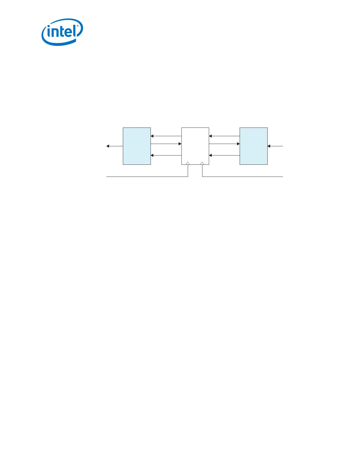
Sync, 8-bit SKP END, and a 24-bit LFSR = 34 Bits. The Rate Match/Clock
compensation block adds or deletes the 4 SKP characters (32-bit) to keep the FIFO
from going empty or full, respectively. If the FIFO is nearly full, it deletes the 4 SKP
characters (32-bit) by disabling write whenever a SKP is found. If the FIFO is nearly
empty, the design waits for a SKP Ordered Set to start and then stops reading the
data from the FIFO, and inserts a SKP in the outgoing data. The actual FIFO core
(memory element) is in the Shared Memory block in the PCS channel.
Figure 265. Rate Match FIFO
SKP
Inserter
Asynchronous
FIFO
SKP
Deleter
data_out data_in
rd_clk
wr_clk
fifo_pempty
rd_en
data
fifo_pfull
wr_en
data
5.4.2.3. RX FIFO (Shared with Standard and Enhanced PCS)
The RX FIFO in each channel ensures a reliable transfer of data and status signals
between the PCS channel and the FPGA fabric. The RX FIFO compensates for the
phase difference between the parallel PCS clock and the FPGA fabric clock. In PIPE
mode, the RX FIFO works in low latency mode.
Related Information
Arria 10 Standard PCS Architecture on page 479
For more information about RX FIFO.
5.4.3. PIPE Interface
This section describes the Auto Speed Negotiation and the Clock Data Recovery
Control of the PIPE interface.
5.4.3.1. Auto Speed Negotiation
Auto speed negotiation controls the operating speed of the transceiver when operating
under PIPE 3.0 modes. By monitoring the pipe_rate signal from the PHY-MAC, this
feature changes the transceiver from PIPE Gen1 operation mode to Gen2 operation
mode, or from PIPE Gen1 operation mode to Gen2 operation mode to Gen3 operation
mode, or vice versa. The PIPE interface clock rate is adjusted to match the data
throughput.
Related Information
Rate Switch on page 237
5. Arria 10 Transceiver PHY Architecture
UG-01143 | 2018.06.15
Intel
®
Arria
®
10 Transceiver PHY User Guide
498