Note:
In Native PHY IP core - PIPE configuration, you must set pipe_rate[1:0]to initiate
the transceiver datarate switch sequence.
2.7.2.2.2. Rate Switch
This section provides an overview of auto rate change between PIPE Gen1 (2.5 Gbps),
Gen2 (5.0 Gbps), and Gen3 (8.0 Gbps) modes.
In Arria 10 devices, there is one ASN block common to the Standard PCS and Gen3
PCS, located in the PMA PCS interface that handles all PIPE speed changes. The PIPE
interface clock rate is adjusted to match the data throughput when a rate switch is
requested.
Table 183. PIPE Gen3 32 bit PCS Clock Rates
PCIe Gen3 Capability Mode
Enabled
Gen1 Gen2 Gen3
Lane data rate 2.5 Gbps 5 Gbps 8 Gbps
PCS clock frequency 250 MHz 500 MHz 250 MHz
FPGA fabric IP clock
frequency
62.5 MHz 125 MHz 250 MHz
PIPE interface width 32-bit 32-bit 32-bit
pipe_rate [1:0]
2'b00 2'b01 2'b10
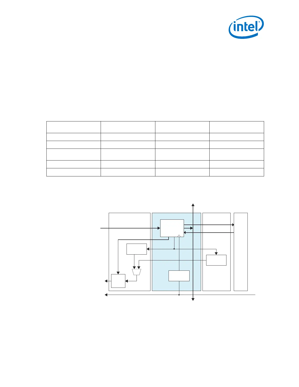
Figure 97. Rate Switch Change
The block-level diagram below shows a high level connectivity between ASN and Standard PCS and Gen3 PCS.
PHYSTATUS
GEN
PHYSTATUS
GEN
TX
FIFO
Gen3 ASN
(Gen1, Gen2, Gen3)
PCS/PMA INF Gen3 PCS
pipe_rate[1:0]
from FPGA Fabric
Control Plane
Bonding Up
Control Plane
Bonding Down
pipe_sw
pipe_sw_done
pipe_phy_status
pll_pcie_clk
PMA
Standard PCS
/2
(for Gen1 Only)
2. Implementing Protocols in Arria 10 Transceivers
UG-01143 | 2018.06.15
Intel
®
Arria
®
10 Transceiver PHY User Guide
237