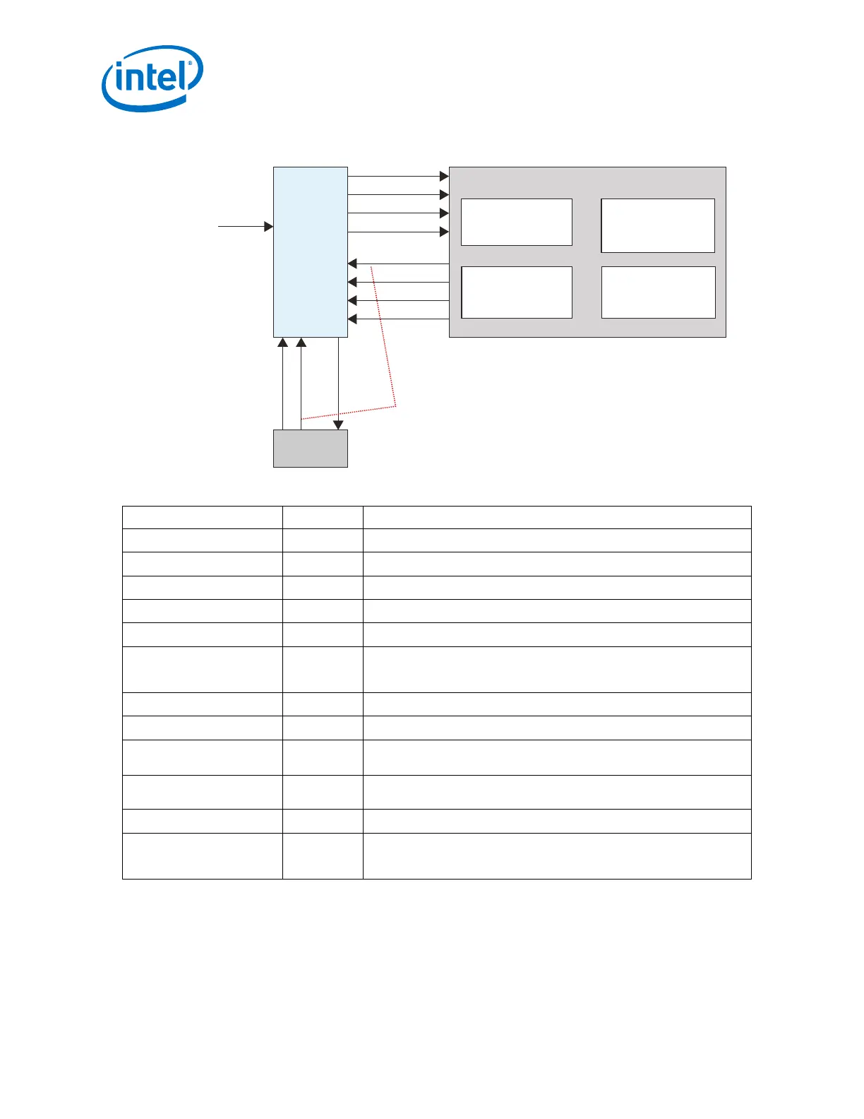
Figure 217. User-Coded Reset Controller, Transceiver PHY, and TX PLL Interaction
User-Coded
Reset
Controller
Transceiver PHY Instance
tx_analogreset
tx_digitalreset
rx_analogreset
rx_digitalreset
tx_cal_busy
rx_cal_busy
rx_is_lockedtoref
rx_is_lockedtodata
Transmit
PLL
pll_powerdown
pll_cal_busy
pll_locked
clock
You can logical OR the pll_cal_busy
and tx_cal_busy signals.
Receiver
PCS
Receiver
PMA
Transmitter
PCS
Transmitter
PMA
Table 250. User-coded Reset Controller, Transceiver PHY, and TX PLL Signals
Signal Name Direction Description
pll_powerdown
Output Resets the TX PLL when asserted high.
tx_analogreset
Output Resets the TX PMA when asserted high.
tx_digitalreset
Output Resets the TX PCS when asserted high.
rx_analogreset
Output Resets the RX PMA when asserted high.
rx_digitalreset
Output Resets the RX PCS when asserted high.
clock
Input Clock signal for the user-coded reset controller. You can use the system
clock without synchronizing it to the PHY parallel clock. The upper limit on
the input clock frequency is the frequency achieved in timing closure.
pll_cal_busy
Input A high on this signal indicates the PLL is being calibrated.
pll_locked
Input A high on this signal indicates that the TX PLL is locked to the ref clock.
tx_cal_busy
Input A high on this signal indicates that TX calibration is active. If you have
multiple PLLs, you can OR their pll_cal_busy signals together.
rx_is_lockedtodata
Input A high on this signal indicates that the RX CDR is in the lock-to-data (LTD)
mode.
rx_cal_busy
Input A high on this signal indicates that RX calibration is active.
rx_is_lockedtoref
Input A high on this signal indicates that the RX CDR is in the lock-to-reference
(LTR) mode. This signal may toggle or be deasserted when the CDR is in
LTD mode.
4.6. Combining Status or PLL Lock Signals
You can combine multiple PHY status signals before feeding into the reset controller as
shown below.
4. Resetting Transceiver Channels
UG-01143 | 2018.06.15
Intel
®
Arria
®
10 Transceiver PHY User Guide
442