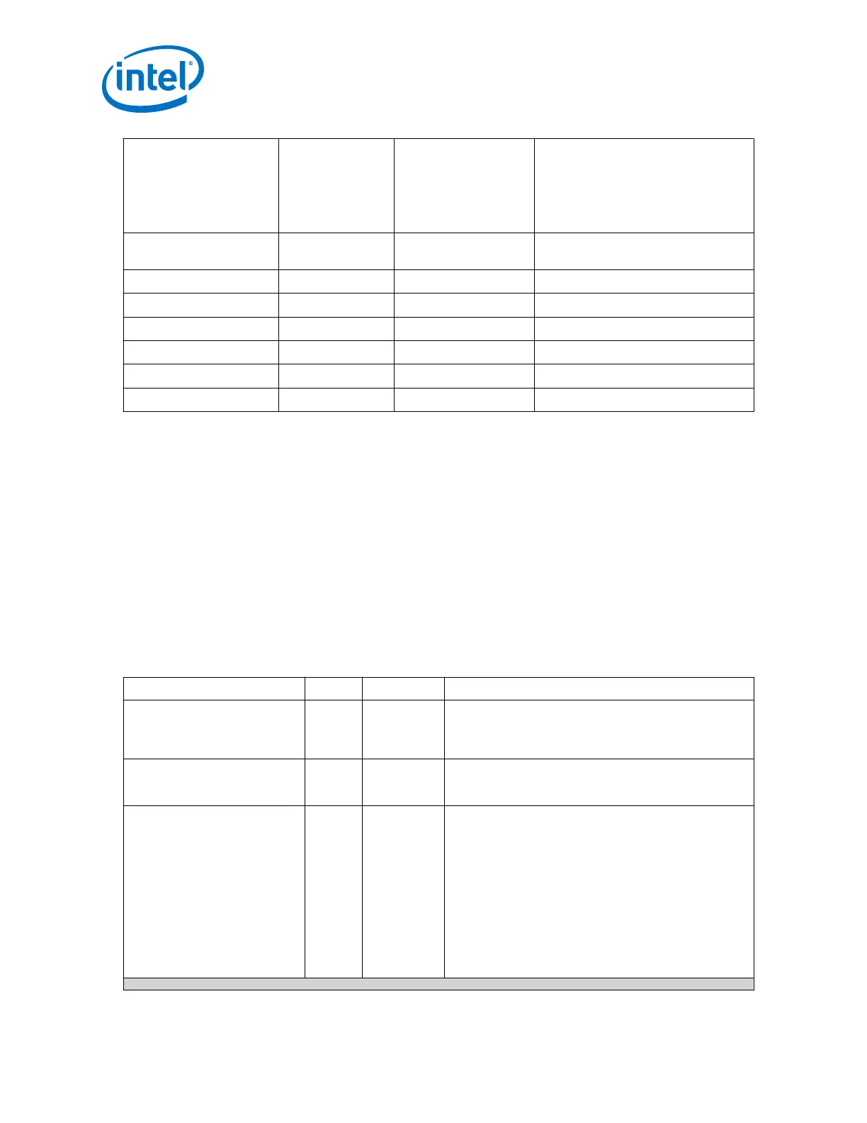
Signal Name Gen1 (TX Byte
Serializer and RX
Byte Deserializer
disabled)
Gen1 (TX Byte
Serializer and RX Byte
Deserializer in X2
mode), Gen2 (TX Byte
Serializer and RX Byte
Deserializer in X2
mode)
Gen3
pipe_tx_deemph
N/A
tx_parallel_data[52
]
N/A
pipe_tx_sync_hdr
N/A N/A
tx_parallel_data[55:54]
pipe_tx_blk_start
N/A N/A
tx_parallel_data[56]
pipe_tx_data_valid
N/A N/A
tx_parallel_data[60]
pipe_rx_sync_hdr
N/A N/A
rx_parallel_data[71:70]
pipe_rx_blk_start
N/A N/A
rx_parallel_data[72]
pipe_rx_data_valid
N/A N/A
rx_parallel_data[76]
Refer to section 6.6 of Intel PHY Interface for PCI Express (PIPE) Architecture for more
information.
Related Information
• PHY IP Core for PCIe (PIPE) Link Equalization for Gen3 Data Rate on page 274
• Intel PHY Interface for PCI Express (PIPE) Architecture
• Bit Mappings When the Simplified Interface is Disabled on page 263
• Using the Arria 10 Transceiver Native PHY IP Core on page 45
2.7.9. fPLL Ports for PIPE
Table 192. fPLL Ports for PIPE
This section contains the recommended settings for this protocol. Refer to Using the Arria 10 Transceiver
Native PHY IP Core for the full range of parameter settings.
Port
Direction Clock Domain Description
Pll_powerdown
Input Asynchronous Resets the PLL when asserted high. Needs to be connected
to a dynamically controlled signal (the Transceiver PHY
Reset Controller pll_powerdown output if using this Intel
FPGA IP).
Pll_reflck0
Input N/A Reference clock input port 0. There are five reference clock
input ports. The number of reference clock ports available
depends on the Number of PLL reference clocks parameter.
tx_serial_clk
Output N/A High speed serial clock output port for GX channels.
Represents the x1 clock network.
For Gen1x1, Gen2x1, connect the output from this port to
the tx_serial_clk input of the native PHY IP.
For Gen1x2, x4, x8, use the tx_bonding_clocks output
port to connect to the Native PHY IP.
For Gen2x2, x4, x8, use the tx_bonding_clocks output
port to connect to the Native PHY IP.
For Gen3x1, connect the output from this port to one of
the two tx_serial_clk input ports on the native PHY IP.
For Gen3x2, x4, x8, connect the output from this port to
the Auxiliary Master CGB clock input port of the ATX PLL IP.
continued...
2. Implementing Protocols in Arria 10 Transceivers
UG-01143 | 2018.06.15
Intel
®
Arria
®
10 Transceiver PHY User Guide
264