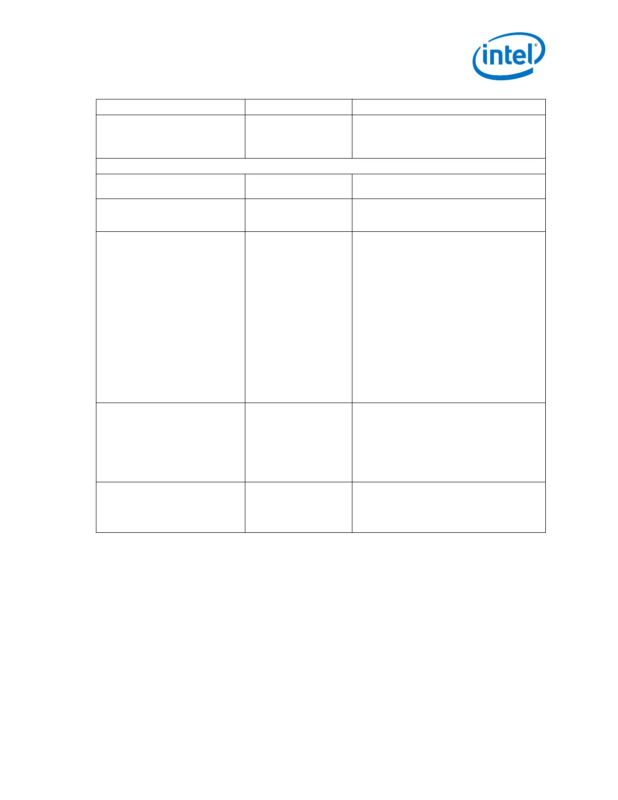
Name Range Description
value of 0 adds no hysteresis. A higher value filters
glitches on the pll_locked signal. Intel
recommends that the amount of hysteresis be
longer than tpll_lock_max_time.
RX Channel
Enable RX channel reset control On /Off When enabled, the IP enables control logic and
status signals for the RX reset signals.
Use separate RX reset per channel On /Off When On, each RX channel has a separate reset
input. When Off, uses a shared RX reset controller
for all channels.
RX digital reset mode Auto, Manual, Expose
Port
Specifies the Transceiver PHY Reset Controller
behavior when the PLL lock signal is deasserted.
The following modes are available:
•
Auto—The associated rx_digitalreset
controller automatically resets whenever the
rx_is_lockedtodata signal is deasserted.
•
Manual—The associated rx_digitalreset
controller is not reset when the
rx_is_lockedtodata signal is deasserted,
allowing you to choose corrective action.
•
Expose Port—The rx_manual signal is a top-
level signal of the IP core. If the core includes
separate reset control for each RX channel,
each RX channel uses its respective
rx_is_lockedtodata signal for automatic
reset control; otherwise, the inputs are ANDed
to provide internal status for the shared reset
controller.
rx_analogreset duration
1-999999999
Specifies the time in ns to continue to assert the
rx_analogreset after the reset input and all
other gating conditions are removed. The value is
rounded up to the nearest clock cycle. The default
value is 40 ns.
Note: Model 1 requires this to be set to 70 µs.
Select the Arria 10 Default Settings
preset.
rx_digitalreset duration
1-999999999
Specifies the time in ns to continue to assert the
rx_digitalreset after the reset input and all
other gating conditions are removed. The value is
rounded up to the nearest clock cycle. The default
value is 4000 ns.
4.4.3. Transceiver PHY Reset Controller Interfaces
This section describes the top-level signals for the Transceiver PHY Reset Controller IP
core.
The following figure illustrates the top-level signals of the Transceiver PHY Reset
Controller IP core. Many of the signals in the figure become buses if you choose
separate reset controls. The variables in the figure represent the following
parameters:
• <n>—The number of lanes
• <p>—The number of PLLs
4. Resetting Transceiver Channels
UG-01143 | 2018.06.15
Intel
®
Arria
®
10 Transceiver PHY User Guide
437