2.6.6.9.4. XAUI PHY Clocks, Reset, and Powerdown Interfaces
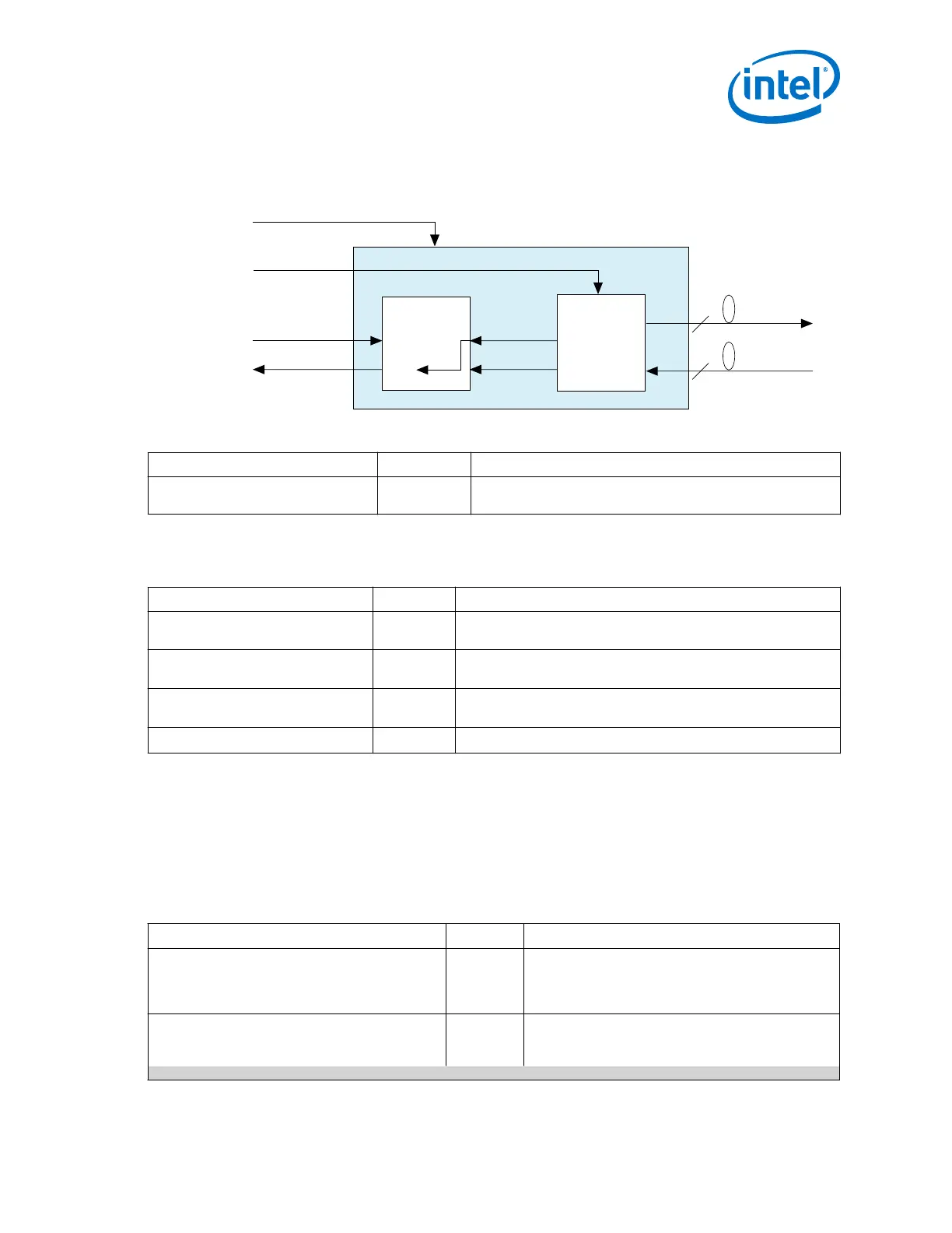
Figure 89. Clock Inputs and Outputs for IP Core with Soft PCS
XAUI Soft IP Core
4 x 3.125 Gbps serial
xgmii_rx_clk
xgmii_tx_clk
pll_ref_clk
phy_mgmt_clk
4
4
Soft PCS
pma_pll_inclk
pma_tx_clkout
tx_clkout
pma_rx_clkout
pll_ref_clk
sysclk
PMA
rx_recovered_clk
Table 174. Clock and Reset Signals
Signal Name Direction Description
pll_ref_clk
Input This is a 156.25 MHz reference clock that is used by the CDR
logic.
2.6.6.9.5. XAUI PHY PMA Channel Controller Interface
Table 175. PMA Channel Controller Signals
Signal Name Direction Description
rx_recovered_clk[3:0]
Output This is the RX clock, which is recovered from the received data
stream.
rx_ready
Output Indicates PMA RX has exited the reset state and the transceiver
can receive data. Synchronous to mgmt_clk.
tx_ready
Output Indicates PMA TX has exited the reset state and the transceiver
can transmit data. Synchronous to mgmt_clk.
pll_cal_busy_i
Input Indicates the PLL calibration status.
2.6.6.9.6. XAUI PHY Optional PMA Control and Status Interface
Use the Avalon-MM PHY Management interface to read the state of the optional PMA
control and status signals available in the XAUI PHY IP core registers. In some cases
you may need to know the instantaneous value of a signal to ensure correct
functioning of the XAUI PHY. In such cases, you can include the required signal in the
top-level module of your XAUI PHY IP core.
Table 176. Optional Control and Status Signals—Soft IP Implementation
Signal Name Direction Description
rx_channelaligned
Output When asserted, indicates that all 4 RX channels are
aligned. Synchronous to mgmt_clk. This signal is
asserted when the RX lanes are fully aligned and ready
to receive data.
rx_disperr[7:0]
Output Received 10-bit code or data group has a disparity
error. It is paired with rx_errdetect which is also
asserted when a disparity error occurs. The
continued...
2. Implementing Protocols in Arria 10 Transceivers
UG-01143 | 2018.06.15
Intel
®
Arria
®
10 Transceiver PHY User Guide
225