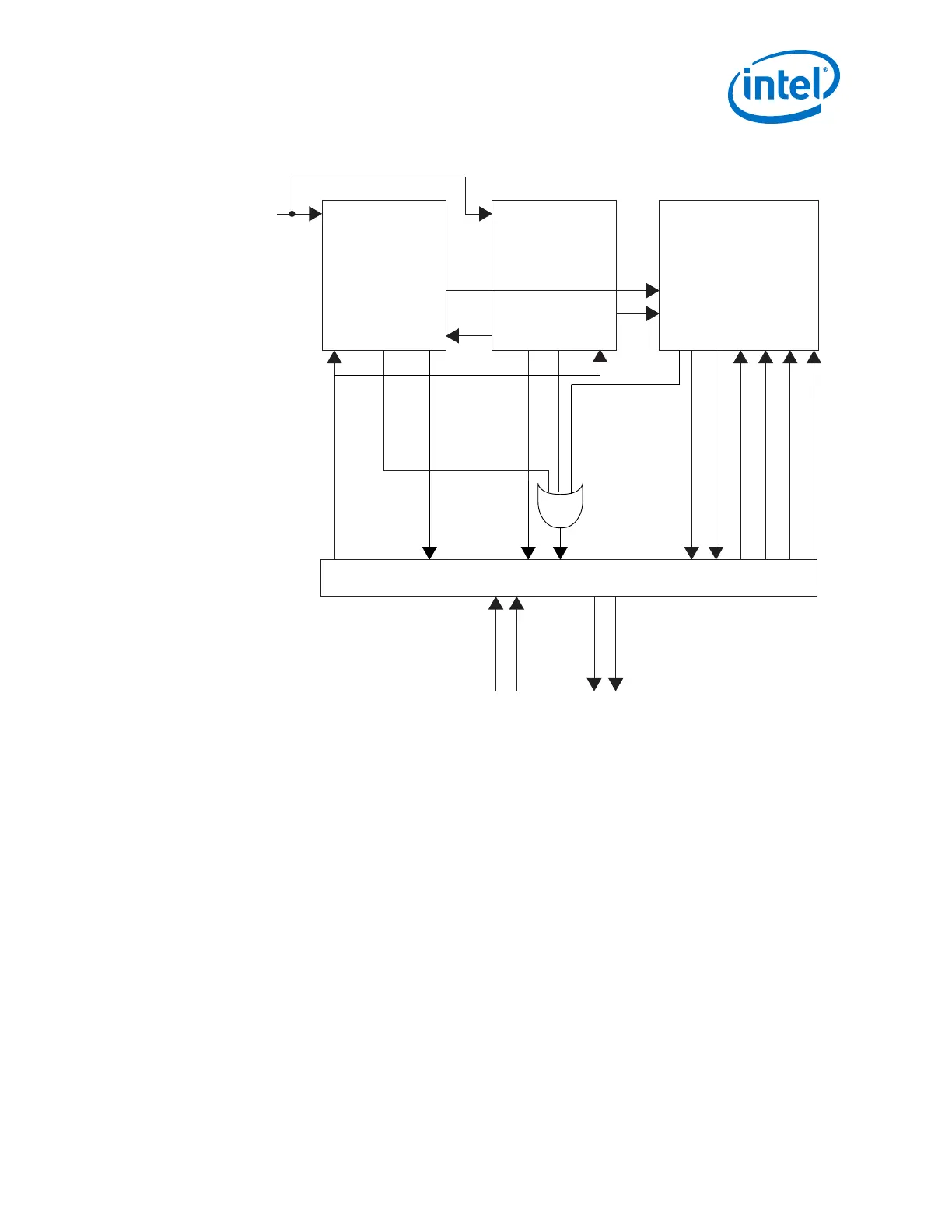
Figure 107. Connection Guidelines for a PIPE Gen3 Design
ATX PLL
and Master
CGB (Gen3)
fPLL
(Gen1/Gen2)
Arria 10
Transceiver
Native PHY
tx_bonding_clocks
tx_serial_clk
pll_pcie_clk
tx_bonding_clocks
pipe_hclk_in
Reset Controller (2)
pll_powerdown
tx_analogreset
tx_digitalreset
rx_analogreset
rx_digitalreset
rx_cal_busy
rx_islockedtoref
clock
reset
tx_ready
rx_ready
pll_cal_busy
pll_locked
pll_locked
pll_cal_busy
pll_refclk
tx_cal_busy
mcgb_aux_clk
(1)
Notes:
(1). If you enable the input pll_cal_busy port in the Transceiver PHY Reset Controller, you
can connect the pll_cal_busy output signals from the PLLs directly to the input
port on the reset-controller without ORing the tx_cal_busy and pll_cal_busy
signals.
(2).
a. If you are using the Transceiver PHY Reset Controller, you must configure the TX digital
reset mode and RX digital reset mode to Manual to avoid resetting the Auto Speed
Negotiation (ASN) block which handles the rate switch whenever the channel PCS
is reset.
b. When the TX digitalreset is in Auto mode, the associated tx_digitalreset controller
automatically resets whenever the pll_locked signal is deasserted. When in Manual
mode, the associated tx_digitalreset controller is not reset when the pll_locked signal
is deasserted, allowing the user to choose what to do.
c. When the RX digitalreset is in Auto mode, the associated rx_digitalreset controller
automatically resets whenever the rx_is_lockedtodata signal is deasserted. When in
Manual mode, the associated rx_digitalreset controller is not reset when the
rx_is_lockedtodata signal is deasserted, allowing the user to choose what to do.
d. If the resets are configured to Auto mode for PIPE designs, then the digital reset
will get asserted automatically when the lock signal is deasserted.
2. Implementing Protocols in Arria 10 Transceivers