Name Direction Clock Domain Description
rx_parallel_data. For each 128-bit word,
rx_patterndetect corresponds to
rx_parallel_data[12].
rx_syncstatus[<n><w>/
<s>-1:0]
Output Asynchronous When asserted, indicates that the conditions required for
synchronization are being met. rx_syncstatus is a part of
rx_parallel_data. For each 128-bit word,
rx_syncstatus corresponds to rx_parallel_data[10].
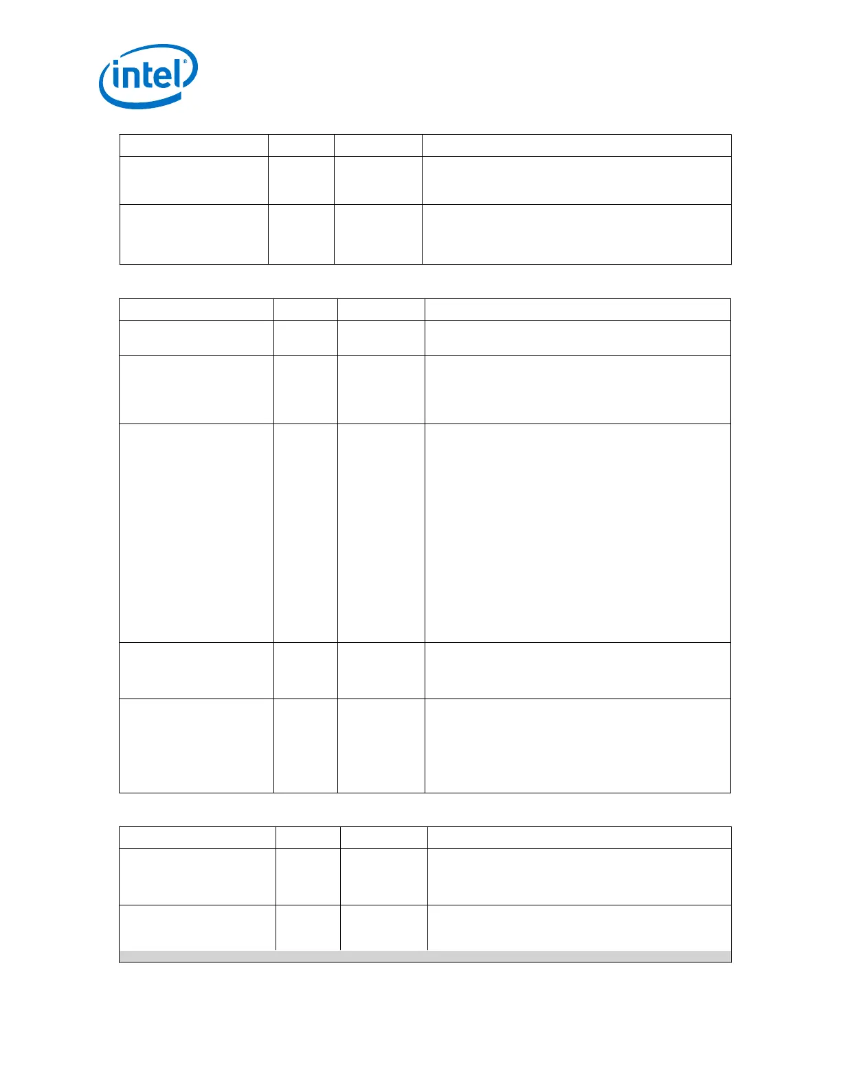
Table 73. Word Aligner and Bitslip
Name Direction Clock Domain Description
tx_std_bitslipboundary
sel[5 <n>-1:0]
Input Asynchronous Bitslip boundary selection signal. Specifies the number of
bits that the TX bit slipper must slip.
rx_std_bitslipboundary
sel[5 <n>-1:0]
Output Asynchronous This port is used in deterministic latency word aligner mode.
This port reports the number of bits that the RX block
slipped. This port values should be taken into consideration
in either Deterministic Latency Mode or Manual Mode of
Word Aligner.
rx_std_wa_patternalig
n[<n>-1:0]
Input Synchronous
to rx_clkout
Active when you place the word aligner in manual mode. In
manual mode, you align words by asserting
rx_std_wa_patternalign. When the PCS-PMA Interface
width is 10 bits, rx_std_wa_patternalign is level
sensitive. For all the other PCS-PMA Interface widths,
rx_std_wa_patternalign is positive edge sensitive.
You can use this port only when the word aligner is
configured in manual or deterministic latency mode.
When the word aligner is in manual mode, and the PCS-PMA
interface width is 10 bits, this is a level sensitive signal. In
this case, the word aligner monitors the input data for the
word alignment pattern, and updates the word boundary
when it finds the alignment pattern.
For all other PCS-PMA interface widths, this signal is edge
sensitive.This signal is internally synchronized inside the
PCS using the PCS parallel clock and should be asserted for
at least 2 clock cycles to allow synchronization.
rx_std_wa_a1a2size[<n>
-1:0]
Input Asynchronous Used for the SONET protocol. Assert when the A1 and A2
framing bytes must be detected. A1 and A2 are SONET
backplane bytes and are only used when the PMA data
width is 8 bits.
rx_bitslip[<n>-1:0]
Input Asynchronous Used when word aligner mode is bitslip mode. When the
Word Aligner is in either Manual (PLD controlled),
Synchronous State Machine or Deterministic Latency ,the
rx_bitslip signal is not valid and should be tied to 0.
For every rising edge of the rx_std_bitslip signal, the
word boundary is shifted by 1 bit. Each bitslip removes the
earliest received bit from the received data.
Table 74. Bit Reversal and Polarity Inversion
Name Direction Clock Domain Description
rx_std_byterev_ena[<n>
-1:0]
Input Asynchronous This control signal is available when the PMA width is 16 or
20 bits. When asserted, enables byte reversal on the RX
interface. Used if the MSB and LSB of the transmitted data
are erroneously swapped.
rx_std_bitrev_ena[<n>-
1:0]
Input Asynchronous When asserted, enables bit reversal on the RX interface. Bit
order may be reversed if external transmission circuitry
transmits the most significant bit first. When enabled, the
continued...
2. Implementing Protocols in Arria 10 Transceivers
UG-01143 | 2018.06.15
Intel
®
Arria
®
10 Transceiver PHY User Guide
90