F2 – Test Menu
Gem-5 User’s Manual 201
Changing the Dwell Time here (by +, -, F6, Ctrl+F6, or Ctrl+F7) does not affect the
voltage applied.
The HVPS is set using a DAC (Digital to Analog Converter) with a range of 0 - 1500
V. The actual voltage is read using an ADC with a range of 0 - 3000 V. Use F1 to set
HV to 0 V for all detectors and F9 to restore normal operating HV values.
The DAC (Set) and ADC (Read) values cannot be compared directly due to their
different resolutions.
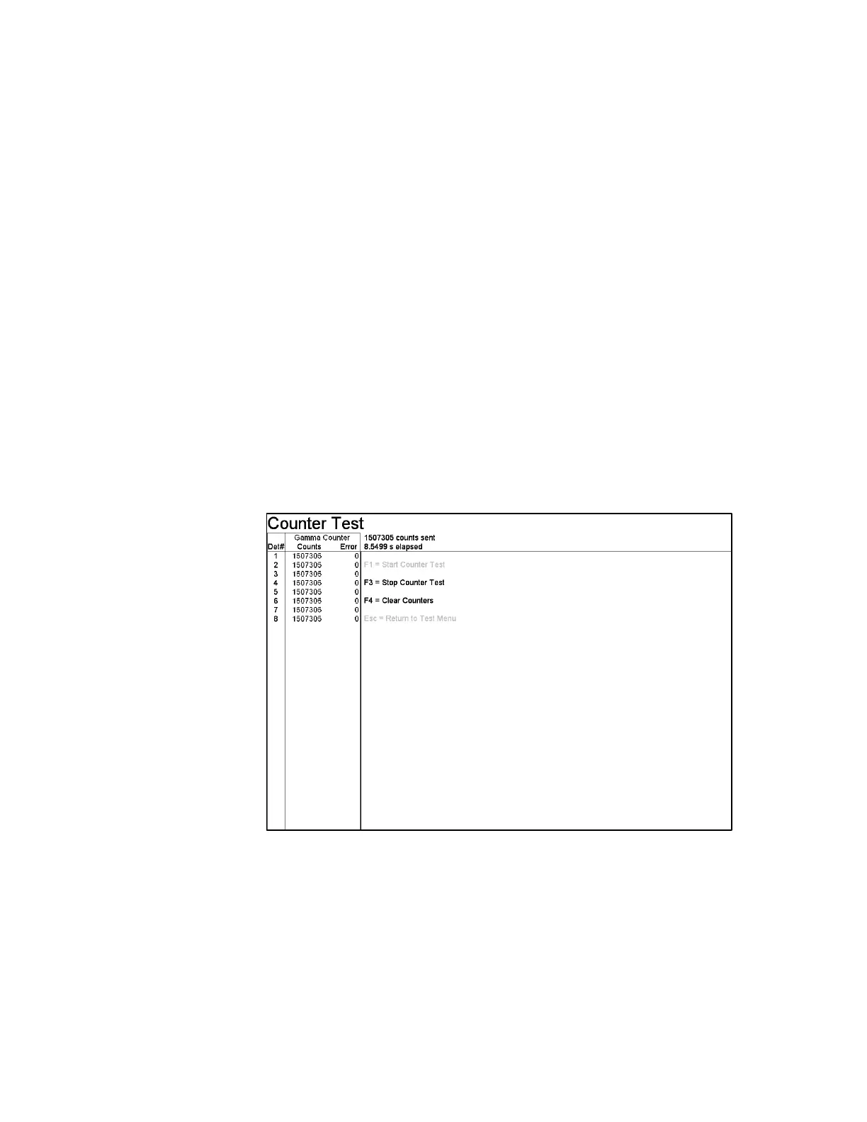
F3 – Counter Test
Each Detector Board has a built-in 24-bit (0–16,777,215) pulse counter device. The
Gamma Counter is Channel 3 and color coded as green. The Counter Test (Figure
92) checks that the digital counter circuits and their line drivers are functioning
correctly. For the test, digital pulses are sent from a test circuit on each board
directly to the counters, in bursts of 43,690 (AAAA hex) pulses. The counter
registers are then read, errors are calculated, and the screen is updated. This is
repeated 384 times until the final count of 16,777,215 (2
24
-1) is reached. At each
update, the current error is compared with the previous maximum error and the
maximum is updated when appropriate. The Error column displays the maximum
error for the duration of the test.
Figure 92 The Counter Test Screen
The test stops when the counters reach their maximum counts or when a manual stop
(F3) is performed. The detector-zone number, counts read, and the maximum error
for each zone are shown. The Error column shows zeros if the digital counting
circuits are operating properly. The total number of pulses sent and the elapsed run
time for the current test are shown at the top of the screen.