Appendix G Specifications – Options
334
Doors
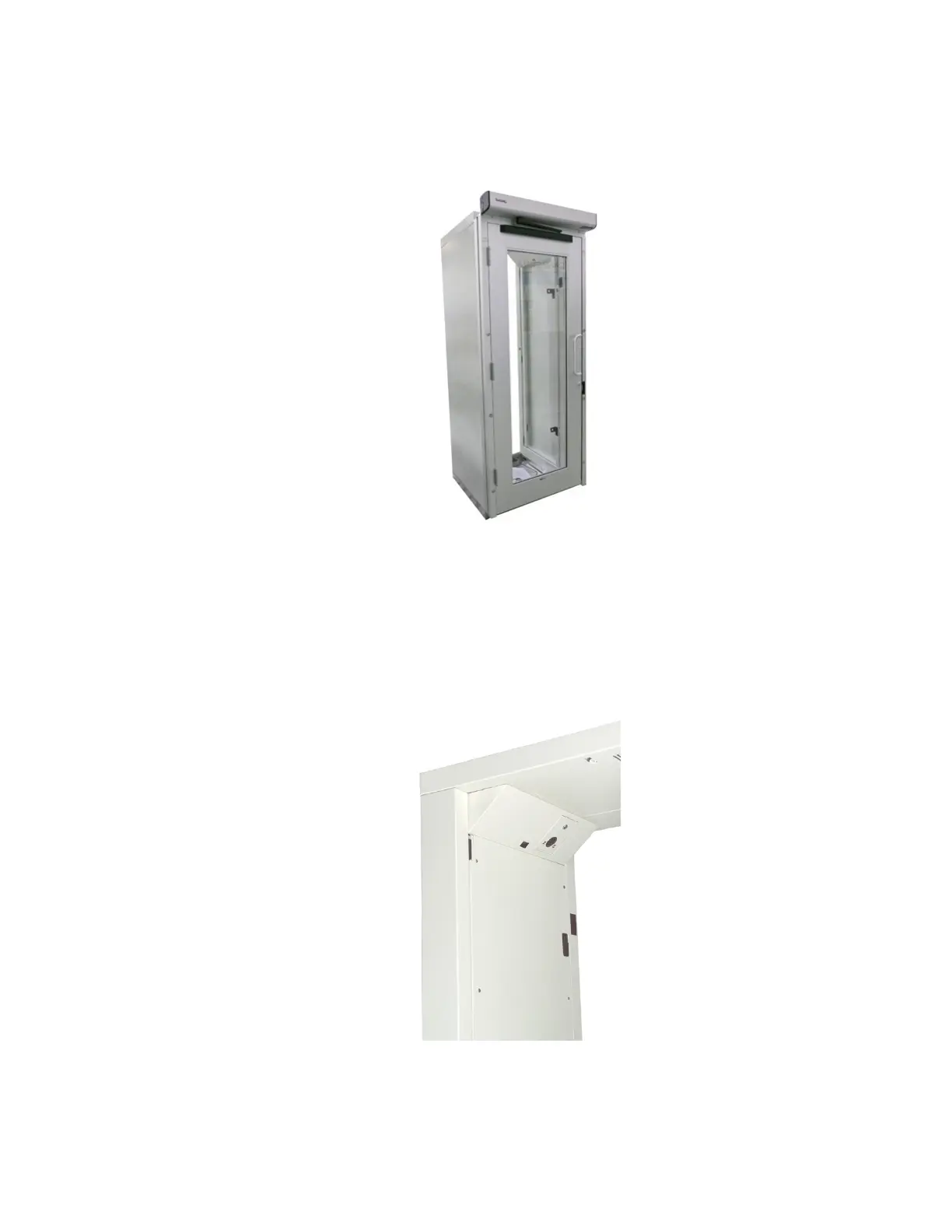
Electric Swing Door for GEM-5
Figure 146 Possible “pinch-point” location for the Electric Barrier Arm
SCN 816115 GEM-5 Electric Auto Swing Door; Exit Only
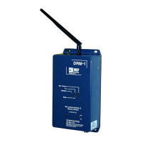
IPCAM212 Camera
Factory installed network Camera Kit For GEM-5 (SCN 7062269).
Figure 147 IPCAM212 for GEM-5