F2 – Test Menu
Gem-5 User’s Manual 207
F7 = TB05 Relay #3; same as Relay #1 above.
F8 = TB06 Relay #4; same as Relay #1 above.
F7 – Timer Tests
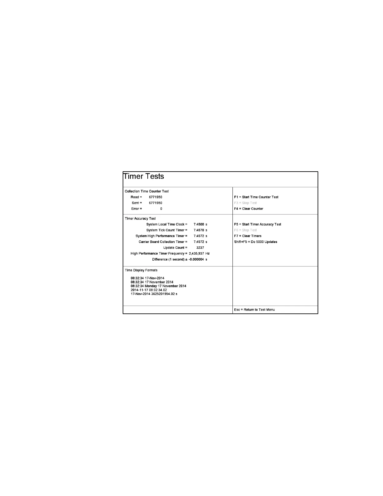
The Timer Tests (Figure 95) check the consistency of the various timers used for
count rate calculations and program control. The crystal controlled oscillator module
on the Carrier Board provides the stable 24 MHz clock frequency used to generate all
necessary timing pulses and clocks for all count rate calculations. A similar circuit
on each Detector Board counts detector pulses. All counters are latched, cleared, and
read simultaneously to ensure accurate count rates.
The screen is split into three areas for timer and time-related tests: Collection Counter
test, Timer Accuracy Test, and Time Display Formats.
Figure 95 The Timer Test Screen
Collection Time Counter Test: The Collection Time Counter Test sends pulses to
the Carrier Board timer and reads back the number of counts. The test is started with
function key F1, stopped with F3, and the counter value is reset to zero using F4.
During the test, pulses are sent in bursts of 43,690 (AAAA hex) pulses. The counter
register is then read, the error is calculated, and the screen is updated. This is
repeated 98306 times until the final count of 4,294,967,295 [2
32
-1] is reached. At
each update, the current error is compared with the previous maximum error and the
maximum is updated when appropriate. The Error reported is the maximum error for
the duration of the test.
To prevent an inappropriately large error being reported if the counter wraps around
to zero [counts > (2
32
-1)], the number of pulses sent is compared with the counts read
and with [counts read + 2
32
] at each update; only the smaller of these errors is used.