Detector Boards
Gem-5 User’s Manual 339
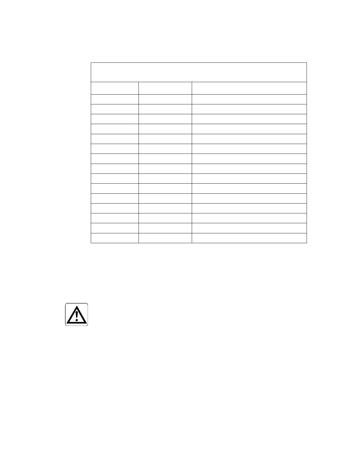
The signal assignments for the 16-wire Detector Serial Interface connector (J7) are
shown in Table 31.
Table 31 Signal Designations for the Detector Serial
Interface Bus (16-wire ribbon cable)
PIN# SIGNAL NAME DESCRIPTION
1 GND GROUND
2 CA COMMAND DIFFERENTIAL LINE A
3 GND GROUND
4 CB COMMAND DIFFERENTIAL LINE B
5 GND GROUND
8 GND GROUND
9 DB DATA DIFFERENTIAL LINE B
10 GND GROUND
11 +12V +12V POWER
12 +12V +12V POWER
14 +12V +12V POWER
15 +12V +12V POWER
Detector Boards
A Detector Board is attached to each installed detector. These boards, which are
software controlled, contain a high voltage supply, preamplifier, pulse shaping
amplifier, discriminator, counters and interface circuitry.
CAUTION:
Remove power before (dis)connecting cables to or
from a Detector Board.
Gamma Detector Boards (i.e., for scintillation detectors) have a single channel
preamplifier/amplifier, pulse shaping amplifier, discriminator, and counter.
A test pulser is provided on-board for amplifier and discriminator testing. The pulse
amplitude is software-controlled and can range from 0 to 2.5 for the pulser and 0 to
0.5 V for the discriminator in gamma counting circuits.
The high-voltage power supply provides regulated positive voltage under software
control. The actual value of the high voltage is measured and used to detect high
voltage failures and for display purposes.