Computer Box
Gem-5 User’s Manual 367
Mode Switch: Should always be set to “L ON” position (output goes low when
object is detected).
Output Switch: Should always be set to “NPN’ position.
Activation can be verified by observing the F6 – Sensor Board Test screen (on page
205) or the small LED indicator built into the sensor.
Computer Box
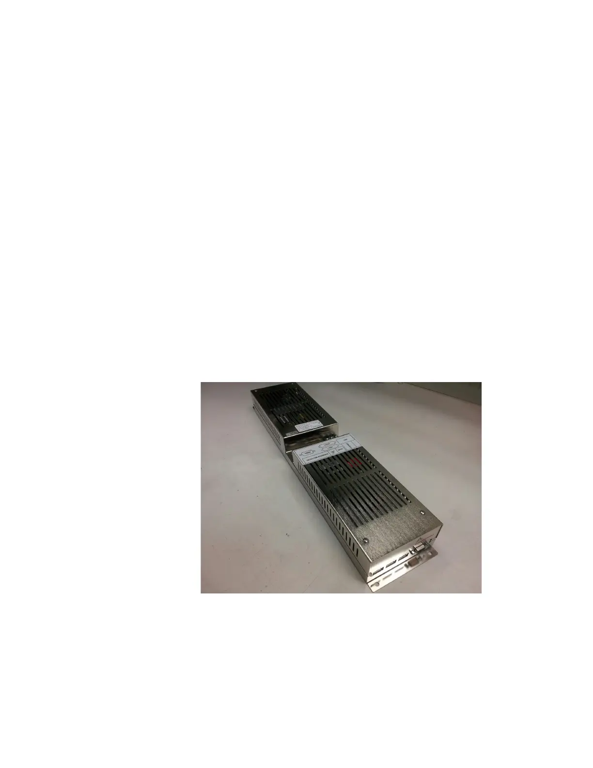
The monitor is equipped with a custom designed computer box (currently used is
Mirion Technologies (Canberra CA) Ltd. PN 7079642) which houses the Carrier
Board (CANBERRA PN 7078120), the computer CPU board (third party) with
Microsoft Windows 7 (or XP if required by a special order) Embedded, and the low
voltage power supply (see Figure 159 below). The chassis is equipped with cooling
fans. The air intake is filtered through a replaceable foam filter pad. The pad can
either be cleaned or replaced when necessary. The computer box is conveniently
accessed as shown in Figure 6 on page 11. This provides access to the computer
connectors, including audio, VGA, network, 6 x USB, ports as well as the system on/
off switch (located at the back – near the power entry connector).
The computer box power switch controls power to the computer board and the low
voltage power supply. Hence this switch removes power from the Carrier Board and
the computer and all components connected to the serial bus.
Figure 159 Computer Box GEM-5
Note: There is no anti-virus software loaded on to the computer since the unit is
configured by default to work in a stand-alone mode. If connecting to a
n
etwork, customer is responsible for ensuring its anti-virus policies are
adhered to. Have the IT department personnel contact local Mirion
Technologies (Canberra CA) Ltd. affiliate for further information.