F2 – Test Menu
Gem-5 User’s Manual 205
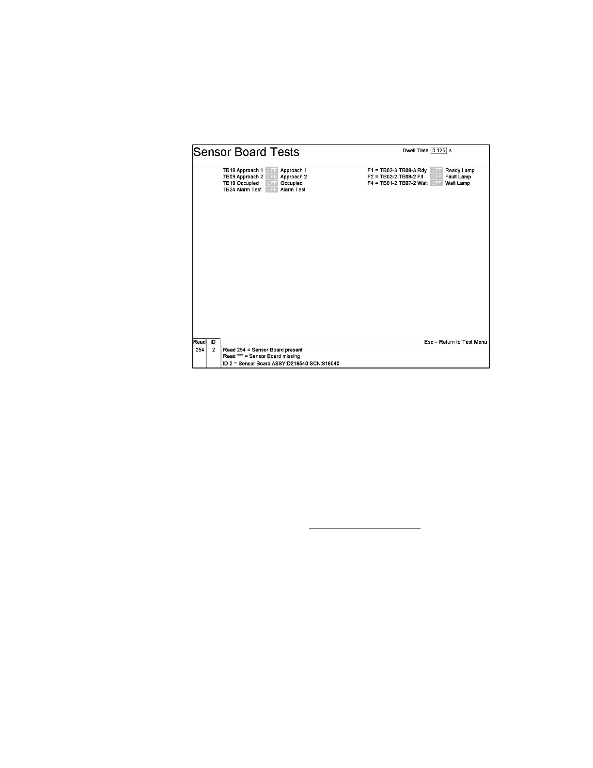
F6 – Sensor Board Tests
The Sensor Board Tests screen (Figure 94) is used to identify the installed Sensor
Board, to test the interface to the sensors and to check the operation of sensors,
annunciator lamps (if installed), and output devices.
Figure 94 The Sensor Board Test Screen
The Sensor Board is connected to the Detector Serial Interface bus and is assigned to
address 254. On entering this screen, the program verifies that the board is present at
that address, as indicated in the Read column. The ID column shows the board model
identifier returned by the board, which can be used to identify it from the list of
Sensor Boards shown at the bottom of the screen.
In general, only the sensors/relays, which are actually in use, are displayed to test
here. One can use Ctrl+F10 to see all terminals on the board.
Labels to left of state boxes are the terminals that are selected on Ctrl+F10 – Factory
Setup, F2 –Operation Configuration (on page 21), F3 – Badge Configuration (on
page 25), and F4 – Access Configuration (on page 28) screens (i.e., they should
match the silkscreen physically printed on the actual board).
The labels to the right of the state boxes are the settings assigned to the
corresponding terminals on Ctrl+F10 – Factory Setup, F2 – Operation
Configuration screen (on page 21), F3 – Badge Configuration (on page 25), and F4 –
Access Configuration (on page 28) screens.
Assuming the board is present and functioning, the state boxes show the current
status of each input sensor and switch. Each sensor/switch indication should turn
green (= ON) when the associated device is activated, in sync with the corresponding
red LED on the Sensor Board. The LEDs on the Sensor Board are generally more