Chapter 6 Diagnostics/Maintenance
200
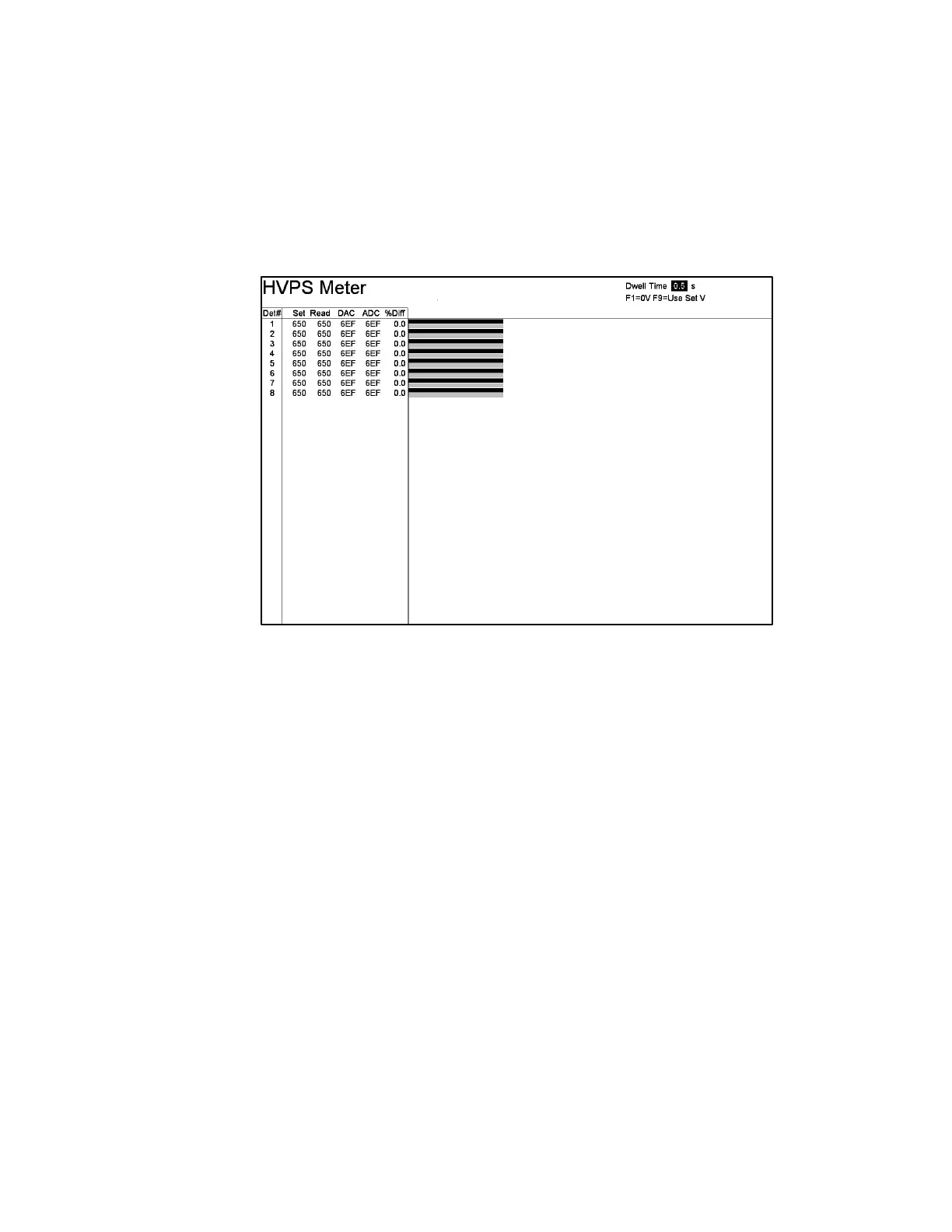
F2 – HVPS Meter
The HVPS Meter screen (Figure 91) tests the HVPS, which is built into each Detector
Board and supplies high voltage to its associated detector. HV settings for normal
operation are F1
−
Optimize Gamma HV procedure (on page 82) or on the
F9
−
Plateau Plot screen (74) and the HV is turned on while on this screen.
Figure 91 The HVPS Meter Screen
The detector number is displayed in the left-hand column; the set voltage and the
measured voltage along with their hexadecimal equivalent values, DAC (Digital to
Analog Converter) set and ADC (Analog to Digital Converter) read, are in the
adjacent columns. The final column displays the difference between the set and
measured values expressed as a percentage of full scale. The bar graph provides a
real-time display of the set and measured voltages. The upper white bar (which
appears black in Figure 91, above) represents the HVPS setting, whereas the lower
grey bar indicates the measured value. The adjustable Dwell Time setting determines
the refresh rate for the display. The Dwell Time remaining for the current update (if
Dwell Time > 1 s) and the full-scale setting are displayed above the bar graph. Use
F6 to restore the factory default Dwell Time setting (1.0 second).
Note that instead of trying to test them, detectors put in Conditional Service on the
F4 – Faults screen show the words “Conditional Service” in place of the data
normally shown. In addition, these detectors are greyed out.
In any case, this screen will only show valid detectors.
Note that F9=Use Set V is used to indicate that the operating Voltage set on
F9 – Plateau Plot screen in will be applied.