Appendix H Component Details – Standard Models
340
The Detector Board communicates with the Carrier Board through the proprietary
Detector Serial Interface bus via a 16-conductor ribbon cable. To avoid voltage losses
across the long cable, the Detector Board generates regulated +1.5V, +3.3V and ±5 V
power from the +12V serial bus power lines. All four three voltages (+1.5V, +3.3V
and ±5 V) have integral LC (inductor-capacitor) noise filtering networks and are
protected by auto-resetting fuses. The Detector Board model number can be
identified by the number stamped on the board. Please refer to for the Detector
Boards currently supported.
To accommodate the different board models, as well as new board versions that
might include differing software requirements, boards have a computer readable
model identification (ID). The Detector Board model number can be determined from
the ID displayed on the Detector Board ID screen which is accessed from the
F2 – Test Menu (on page 208), or from the Board Marking stamped on the board as
mentioned above. The Monitor software uses the ID to determine the default high
voltage setting, as shown in Table 32 and Table 42 on page 352.
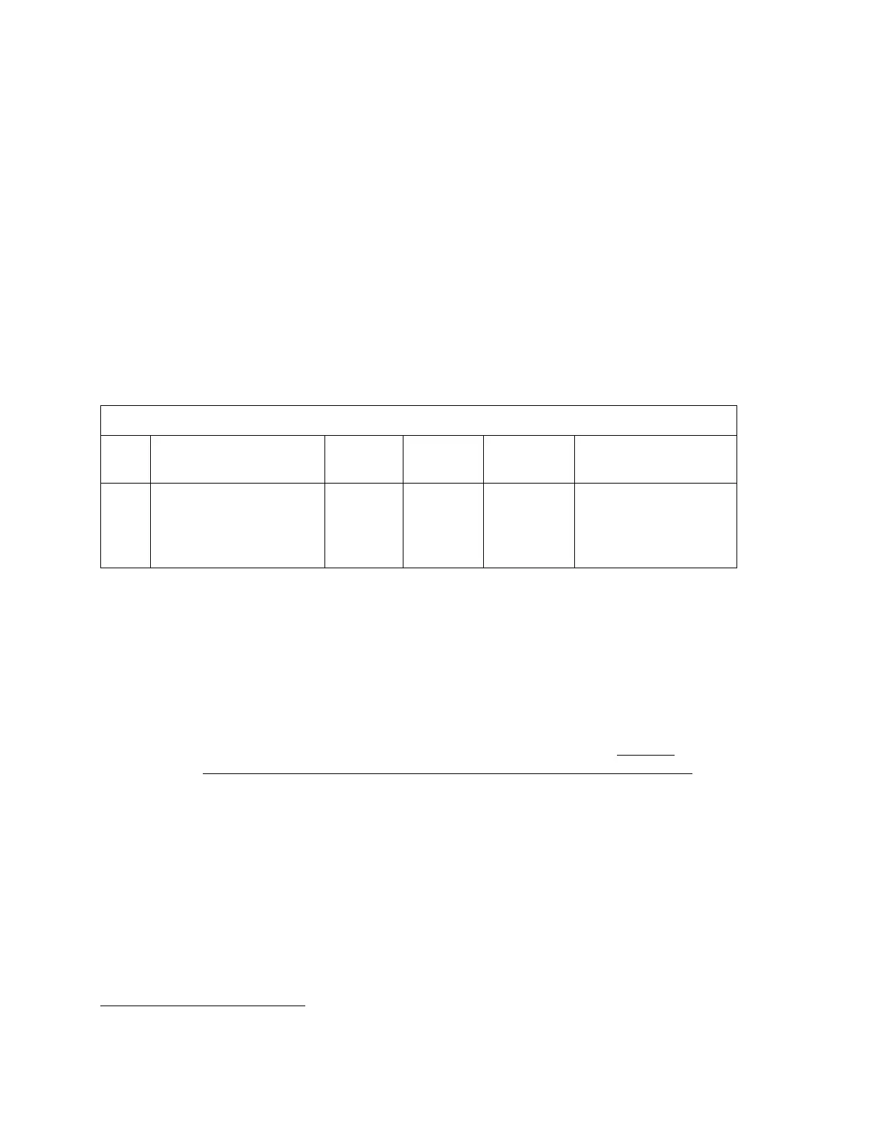
Table 32 Standard Detector Board(s)
ID Board Marking SCN
Max
Voltage
Default
Voltage
Board Type
125 C216112
B216103 and C216102
B216108 and C216107
816112
816102
816107
1500
650
Gamma Interface
Board
19
Digital Board
Analog Board
Board Settings
The only board setting that may require changing is the Board Id switch SW1. This
must be changed only when a board is replaced or moved to a different position in the
unit. This is an 8-position DIP switch that allows encoding (in binary format) the
actual number (or position) of a board in the system. Refer to Table 33. The monitor
will not function correctly unless all detector boards are setup with the proper Id.
Refer to the detector layout diagrams shown in Detector Numbers and Positions
starting on page 328 of these Appendices for detector numbering. The least
significant bit is switch position 1; the most significant bit is switch position 8. To
activate a bit the respective switch has to be in OFF position. For example, detector
#5 should be set to 10100000 (1=OFF, 0=ON).
19
Gamma Detector Board Assembly (SCN 816112) includes Digital Board (SCN 816102) and Analog Board (SCN 816107)