Chapter 6 Diagnostics/Maintenance
218
7. Review results to confirm that the proposed Self Shield Factors are valid and
not merely statistical aberrations. Zones that are geometrically similar should
have very similar factors. See Footnote 13 on page 215 for the special case for
gamma detectors.
8. Press F8 to apply the results to Gamma zones for the selected “Self Shield
Type” as shown Figure 102 on page 217, only Gamma zones are considered.
9. Press Esc when done to return to the Shift+F2 – Additional Test Menu.
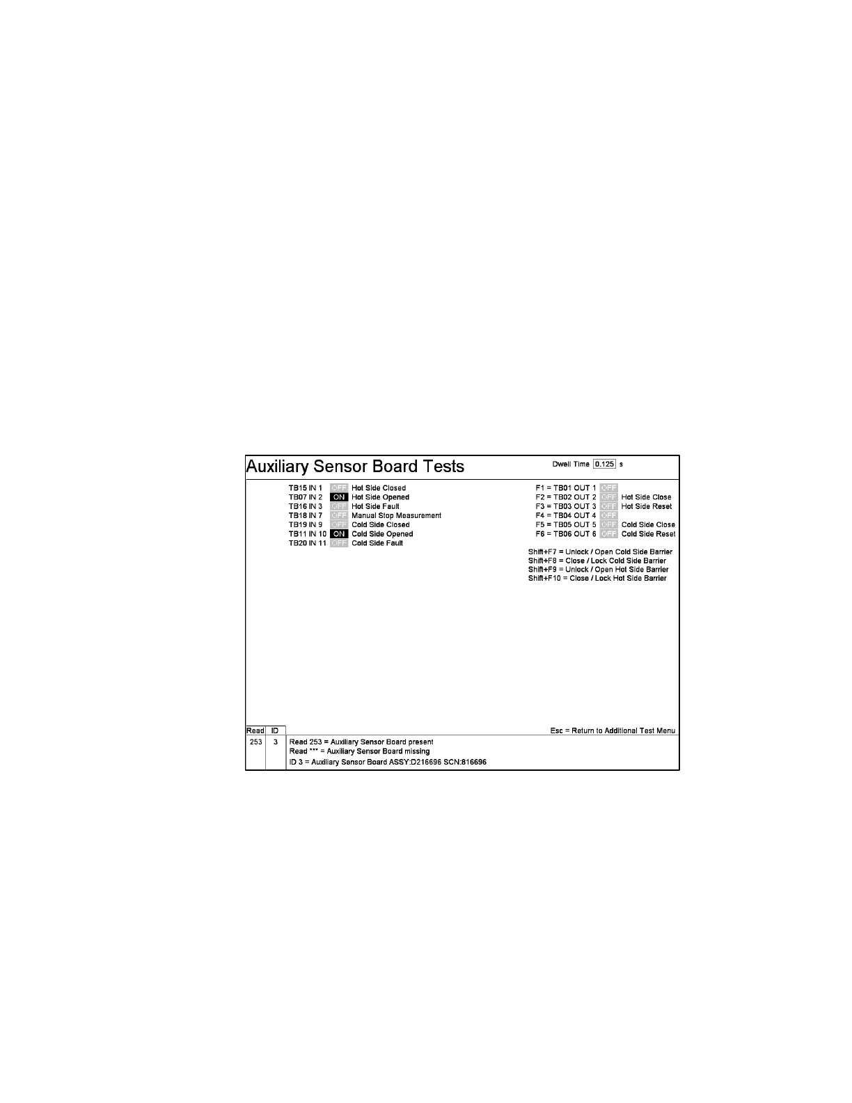
F3 – Test Auxiliary Sensor Board
The Auxiliary Sensor Board Test screen (Figure 103) only appears if Auxiliary
Sensor Board Installed is set to “Yes” on the F1 – Model Selection screen (on page
18). It is used to identify the installed Auxiliary Sensor Board, to test the interface to
the sensors and to check the operation of sensors, annunciator lamps (if installed),
and input/output devices.
Figure 103 Auxiliary Sensor Board Tests Screen
The Auxiliary Sensor Board is connected to the Detector Serial Interface bus and is
assigned to the address 253. On entering this screen, the program verifies that the
board is present at that address, as indicated in the Read column. The ID column
shows the board model identifier returned by the board, which can be used to identify
it from the list of Boards shown at the bottom of the screen.
In general, only the sensors/relays, which are actually in use, are displayed to test
here. One can use Ctrl+F10 to see all terminals on the board.