Appendix K Preventative Maintenance – Options
372
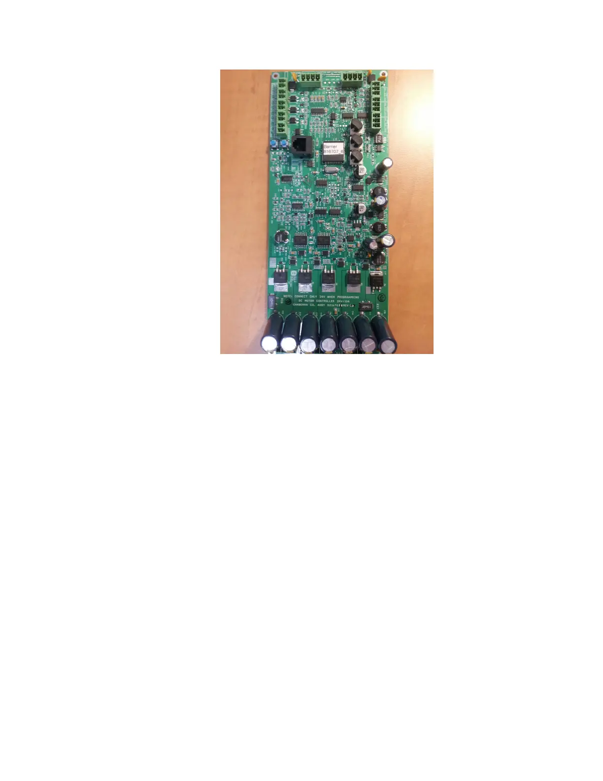
Figure 160 Picture of the DC Motor Control Board (SCN 816701)
Inputs and Outputs
Refer to Figure 160 above.
• J13: Position limit switch input; labeled LIMIT1.
• J12: Position limit switch input; labeled LIMIT2.
• J10: Optical sensor input; labeled OPTO.
• J1: Incremental encoder input; labeled ENCODER.
• J18: Open/close command input; labeled OPEN/CLOSE.
• J14: Fault condition output; labeled FAULT.
• J15: Limit 1 switch output; labeled OUT1.
• J16: Limit 2 switch output; labeled OUT2.
• J11: Reset input; labeled RESET
• J7: 24V power input (with the polarity marking); labeled POWER
• J9: Electromagnet brake output; labeled BREAK
• J8: DC motor output; labeled MOTOR