Chapter 6 Diagnostics/Maintenance
224
YES on Magenta: Fault, and set to WARN or AUTO for unit out of service if faulted.
The fault status of all detectors in the unit is provided in the color-coded inset
diagram on the right-hand side of the screen (see table below). The currently selected
zone is identified by cross-hatching. A detector is shown in grey if it is not part of
any sum zone of the type (pair, triple, etc.) currently selected.
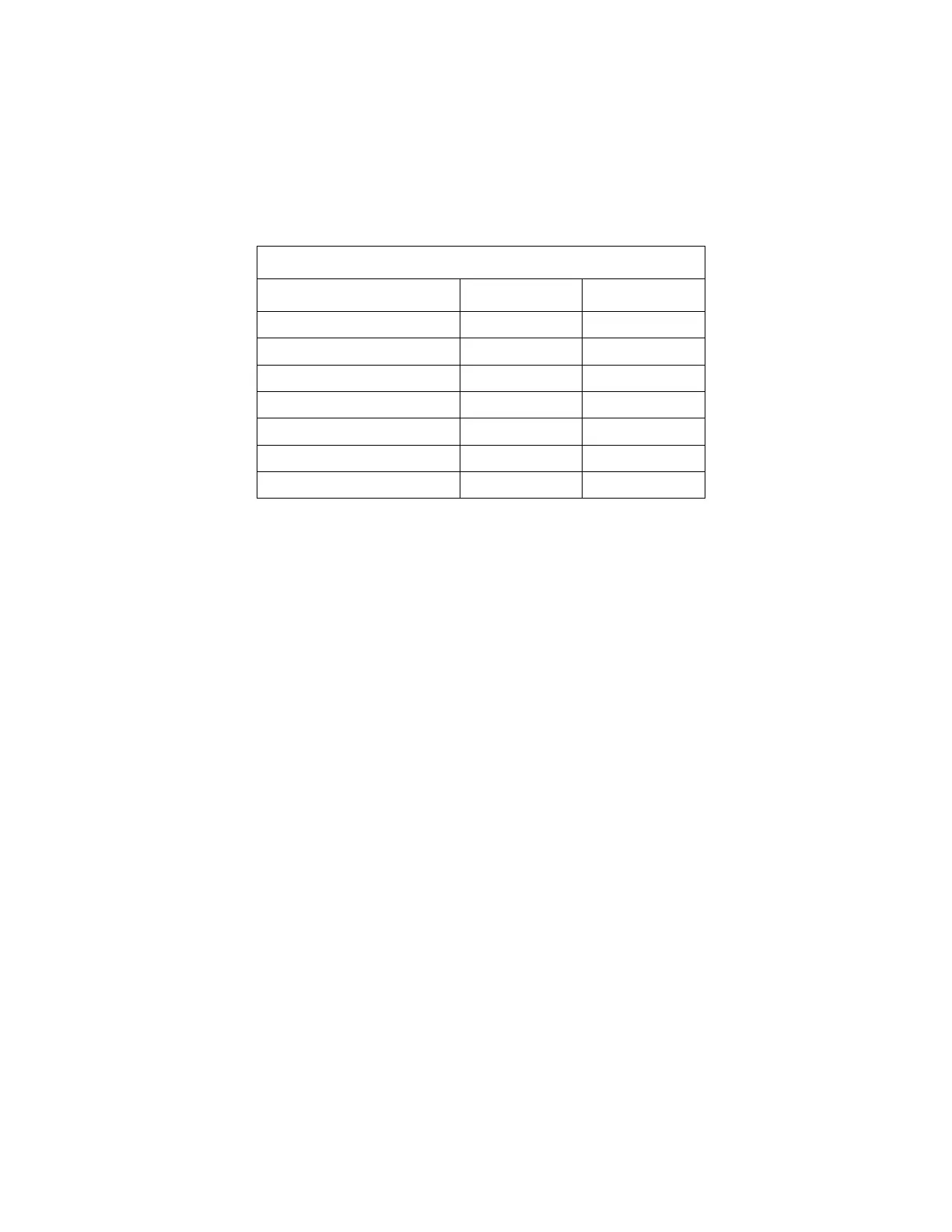
Table 13 Detector Layout Diagram Color Codes
Fault Conditioned Color
Item Not Enabled N/A Not Shown
None No Light Green
None Yes Dark Green
Other Fault Yes Yellow
N/A N/A Grey
Corrective action should be taken, based on the screen indications, to replace or
repair all detectors that are indicated as faulted on this screen. If one or more
detection zones are in conditional service then use F1 or F5 to restore the zone(s) to
normal service. If “Conditional Service Elapsed” is indicated, (see F4 – Out of
Service Causes screen (on page 141), Conditional Service Allowed, and then press
F5 to clear all conditional masks. Next press F4 to clear the latched error flags. This
should restore the screen to all green, permitting the monitor to return to normal
service.
Note also that for Conditional Service:
• When viewing sum zones, detectors that are part of a sum zone in conditional
service are shown in dark green. This is done to show detectors that are part
of selected sum zone in light green if it is in normal service.
• The HV is turned off for detectors in conditional service.
• The counter for detectors in conditional service are not read and zero counts
is added for these detectors into the normal service sum zones to which they
belong.
If the underlying detector fault is still not repaired, the unit can be placed in
conditional service subject to conditions (see F1 below), provided that error flags
were cleared using F4 (or F5, F4) as explained above.
The Faults screen includes additional diagnostic information, such as the operational
status of the Carrier Board, the Sensor Board and the Auxiliary Board (if installed),
the hardware model number, the version number and compilation date of the control
program, and the oldest calibration date for any detection zone. No Calibration
Date is shown if any single detection zone (i.e. a zone consisting of just one