Keypad Replacement
Service Manual 10-7
10. Place the unit on its back. Remove the strap or cable tie from the handle, and re-
open the unit.
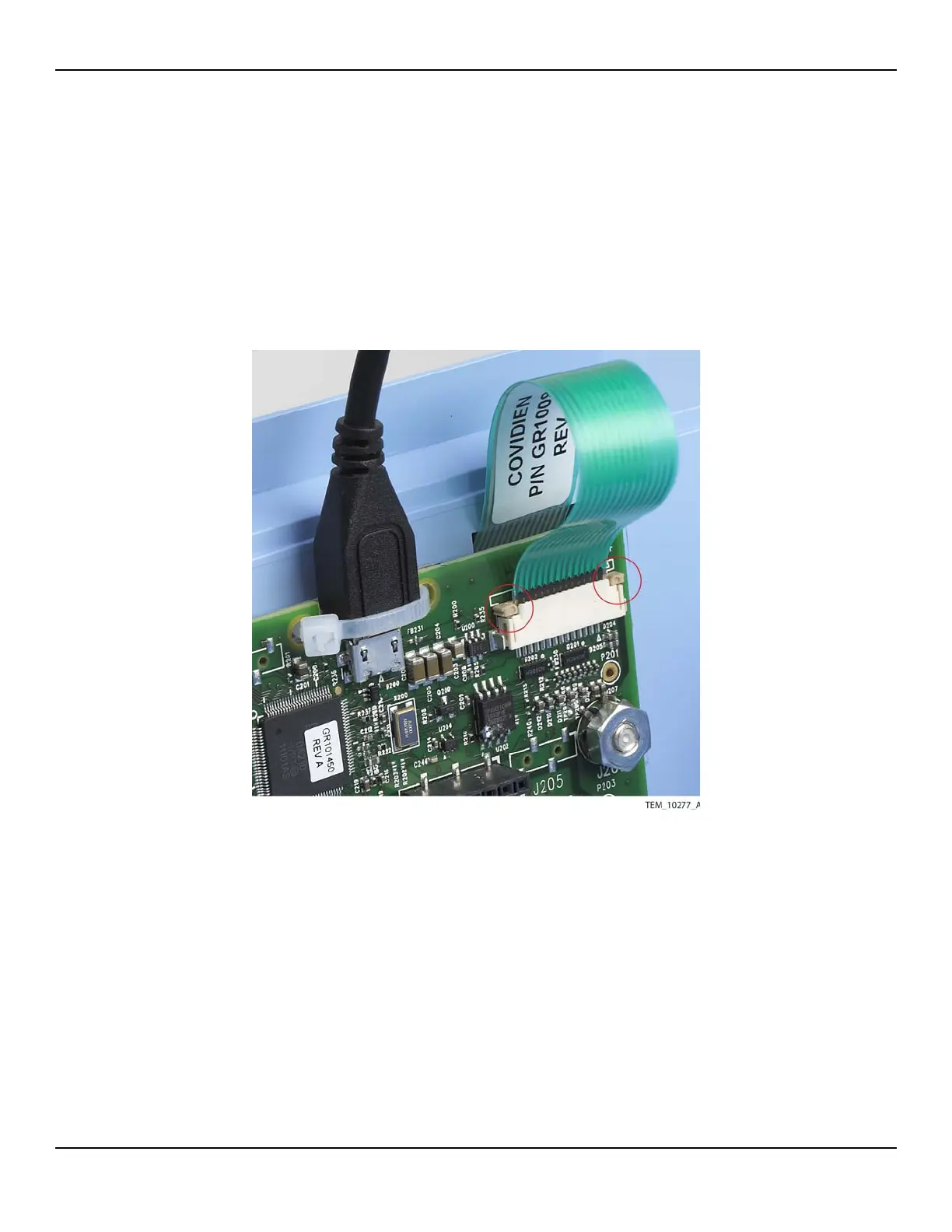
11. On the UI PCBA, slide the locking bar up from the J204 connector, and slide the
keypad cable completely into the connector in front of the locking bar. Press down
on both sides of the locking bar to secure the cable. The locking bar must be com-
pletely seated on both sides (Figure 10-6).
Figure10-6.Keypad Cable Secured by Locking Bar
12. Follow the procedure Rejoining the Front and Rear Enclosures on page 9-5.
13. Perform the following tests:
a. Keypad Test on page 7-5.
b. Electrical Safety Tests on page 7-14.