Internal Component Replacement (Inside Rear Enclosure)
11-54 Service Manual
outside of the enclosure. Tighten the screws to 0.18 to 0.27 N-m (1.6 to 2.4
lb-in).
24. Remove the strap or cable tie from the hose duct adapter.
25. Reconnect the cables to the Power PCBA as follows (Figure 11-43 on page 11-46):
a. Connect the heater cable to the 5-pin P114 connector. Make sure that the
connector is oriented as shown in Figure 11-43, and that it is fully seated.
b. Connect the thermostat cable to the 2-pin P113 connector. Make sure that
the connector is oriented as shown in Figure 11-43, and that it is fully seated.
c. Connect the fan cable to the 4-pin P111 connector. Make sure the connector
latch engages.
d. Connect the thermistor cable to the 2-pin P108 connector. Make sure the
connector latch engages.
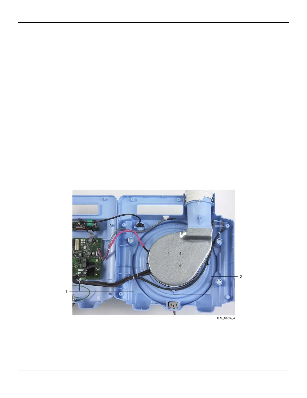
26. Make sure that thermostat cable is routed as shown in Figure 11-52. It must be
positioned to the inside of the adjacent screw boss and pole clamp mounting bolt
and inside the tabs around the fan assembly.
Figure11-52.Routing of Cables around Fan Assembly
1 Cable Ties
(Heater Cable to Thermostat Cable)
2 Thermostat Cable
Routing Tabs