Internal Component Replacement (Inside Rear Enclosure)
11-32 Service Manual
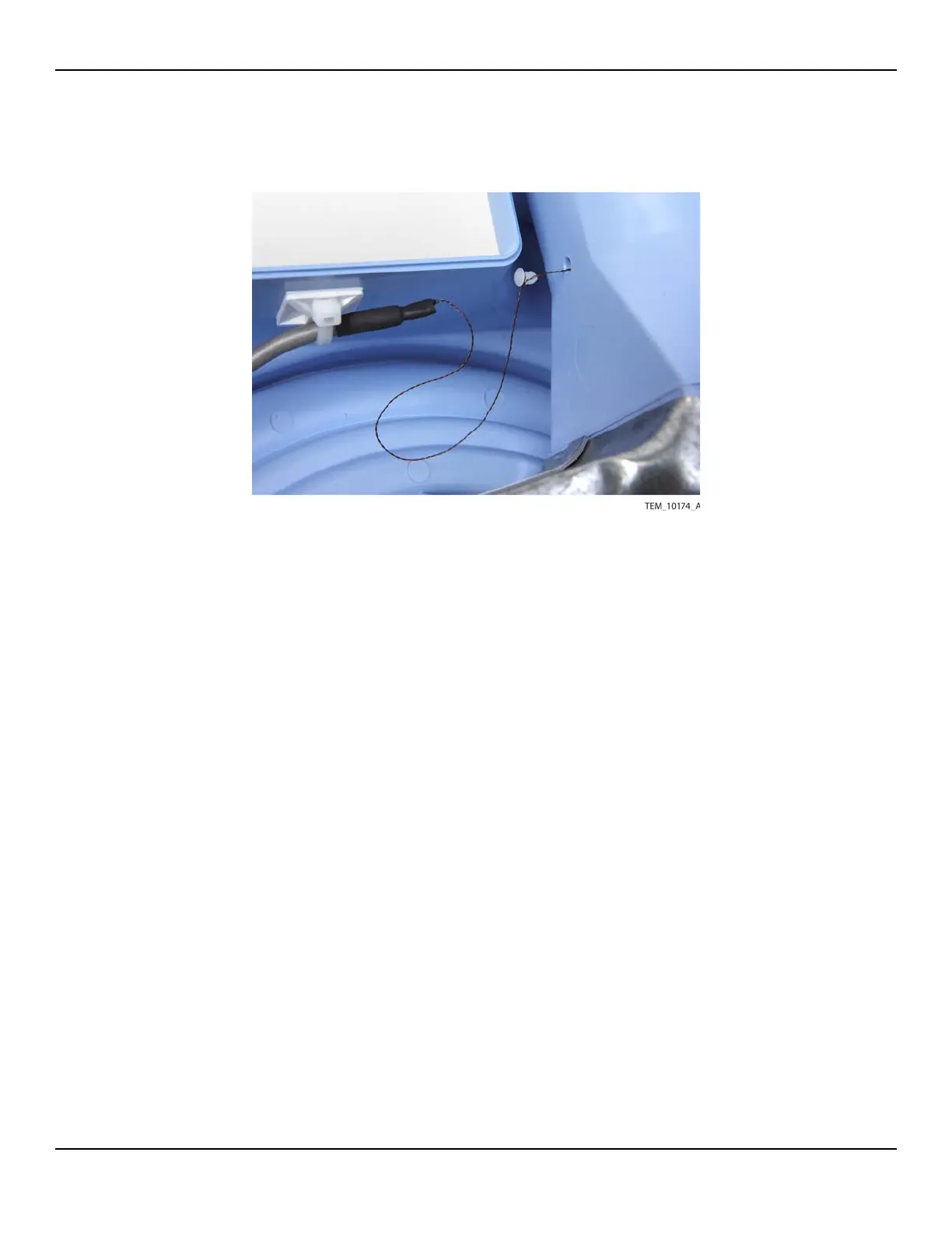
Figure11-29.Inserting Thermistor Wire and Rivet
13. Connect the two thermostat wires to the thermostat as shown in Figure 11-24 on
page 11-27. Note that the wires can be connected to either terminal, but for con-
sistency across units they should be connected as shown.
14. Make sure that thermostat cable is routed as shown in Figure 11-22 on
page 11-25. It must be positioned to the inside of the adjacent screw boss and
pole clamp mounting bolt and inside the tabs around the fan assembly.
15. Follow the procedure Rejoining the Front and Rear Enclosures on page 9-5.
16. Perform the following tests:
a. Power-On Test on page 7-3.
b. Temperature Accuracy Test on page 7-8.
c. Thermostat Test on page 7-11.
d. Electrical Safety Tests on page 7-14.