Rear Enclosure Replacement
Service Manual 12-31
c. Supporting the USB connector, rotate the rear enclosure so that you can
access the outside. Secure the connector by installing the two screws from the
outside of the enclosure. Tighten the screws to 0.18 to 0.27 N-m (1.6 to 2.4
lb-in).
31. Remove the strap or cable tie from the hose duct adapter.
32. Reconnect the cables to the Power PCBA as follows (Figure 12-15 on page 12-20):
a. Connect the heater cable to the 5-pin P114 connector. Make sure that the
connector is oriented as shown in Figure 12-15, and that it is fully seated.
b. Connect the thermostat cable to the 2-pin P113 connector. Make sure that
the connector is oriented as shown in Figure 12-15, and that it is fully seated.
c. Connect the fan cable to the 4-pin P111 connector. Make sure the connector
latch engages.
d. Connect the thermistor cable to the 2-pin P108 connector. Make sure the
connector latch engages.
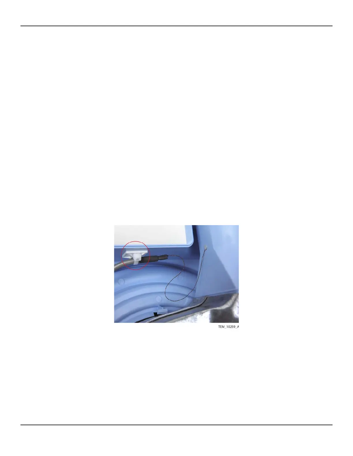
33. Position the thermistor cable against the tie mount on the enclosure as shown in
Figure 12-28. Secure the cable with a cable tie and trim the end of the cable tie.
Figure12-28.Thermistor Cable Secured