Enclosure Replacement
12-32 Service Manual
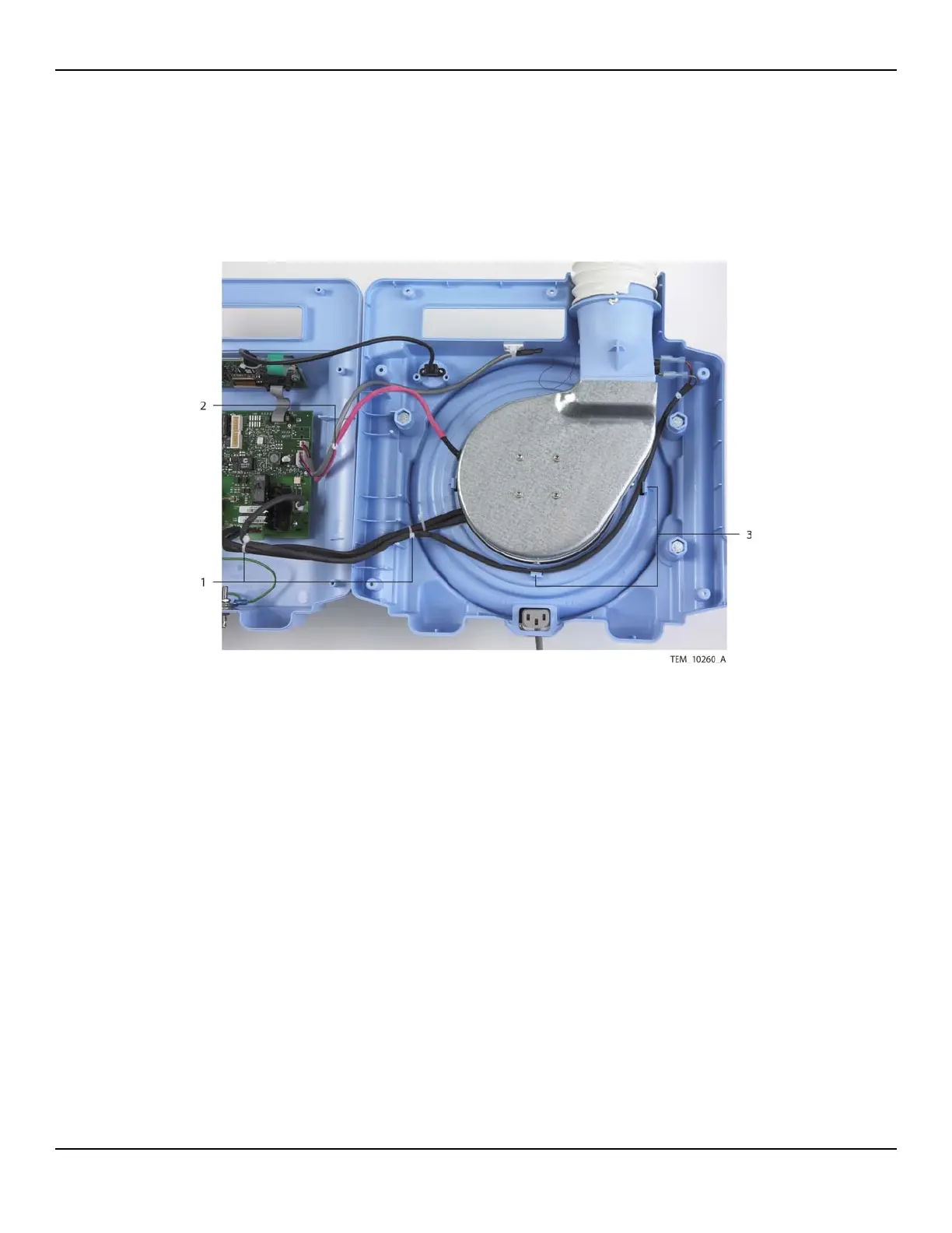
34. Place a cable tie around the fan cable and thermistor cable approximately 10 cm
(4 inches) from the Power PCBA connectors (Figure 12-29). Trim the end of the
cable tie.
Figure12-29.Cable Ties and Routing of Cables
35. Make sure that thermostat cable is routed as shown in Figure 12-29. It must be
positioned to the inside of the adjacent screw boss and pole clamp mounting bolt
and inside the tabs around the fan assembly.
36. Using two cable ties, secure the thermostat cable to the heater cable as follows
(Figure 12-29):
a. Place one cable tie around the cables approximately 5 cm (2 inches) from
where the heater cable exits below the fan assembly.
b. Place the other cable tie around the cables approximately 10 cm (4 inches)
from the heater cable connector (P114) on the Power PCBA.
c. Trim the ends of the cable ties.
1 Cable Ties
(Thermostat Cable to Heater Cable)
3 Thermostat Cable
Routing Tabs
2 Cable Tie
(Fan Cable to Thermistor Cable)