Equipotential Stud Replacement
Service Manual 10-57
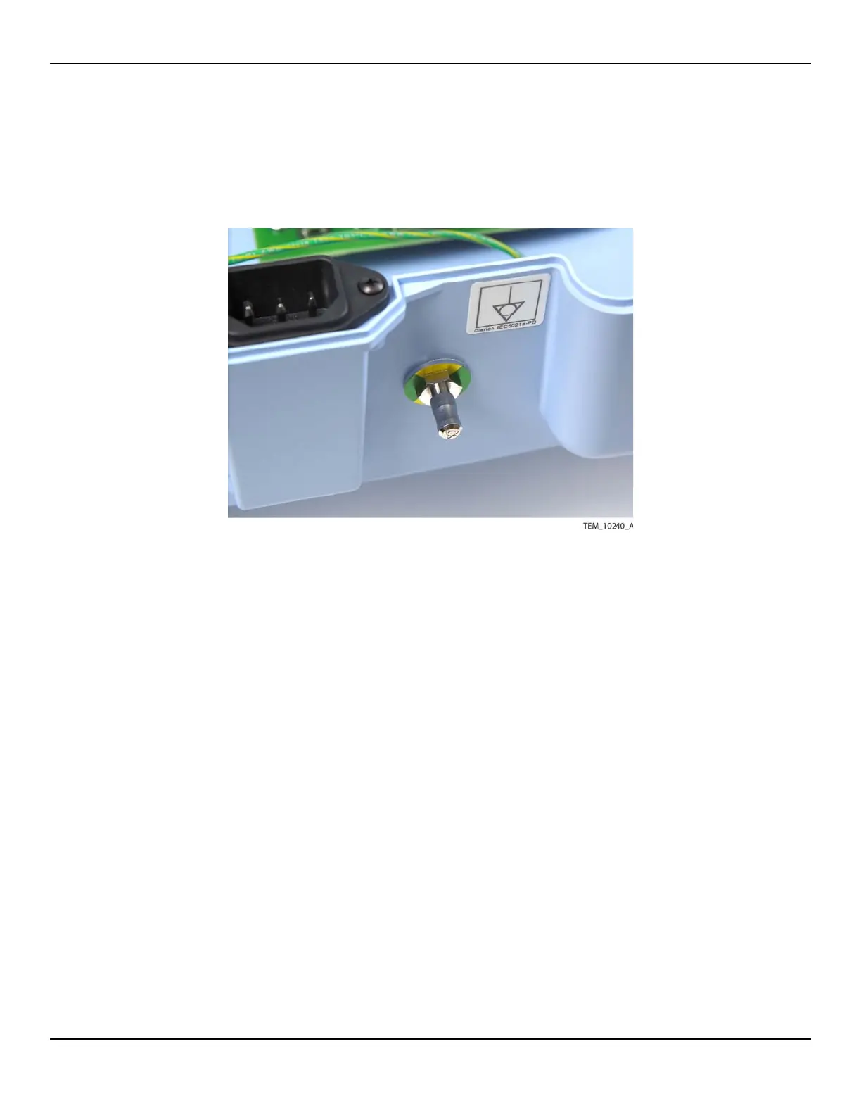
4. From the bottom of the enclosure, insert the threaded end of the stud into the
hole (Figure 10-42).
Figure10-42.Equipotential Stud and Washer
5. Connect the cables to the equipotential stud as follows (Figure 10-41 on
page 10-56):
a.
Place the AC power inlet ground cable terminal on the threaded end of the stud.
b. Place a lock washer on top of the terminal.
c. Place a nut on top of the lock washer. Tighten the nut to 3.2 to 3.8 N-m (28.3
to 33.6 lb-in).
d. Place the power supply ground cable terminal on top of the nut.
e. Place a lock washer on top of the terminal.
f. Place a nut on top of the lock washer. Tighten the nut to 3.2 to 3.8 N-m (28.3
to 33.6 lb-in).
6. Follow the procedure Rejoining the Front and Rear Enclosures on page 9-5.
7. Perform the following tests:
a. Run an ohmmeter or digital multi-meter with resistance function between the
ground pin on the AC power inlet and the equipotential stud. The value must
be <1 Ohm.
b. Power-On Test on page 7-3.
c. Electrical Safety Tests on page 7-14.