Internal Component Replacement (Inside Front Enclosure)
10-16 Service Manual
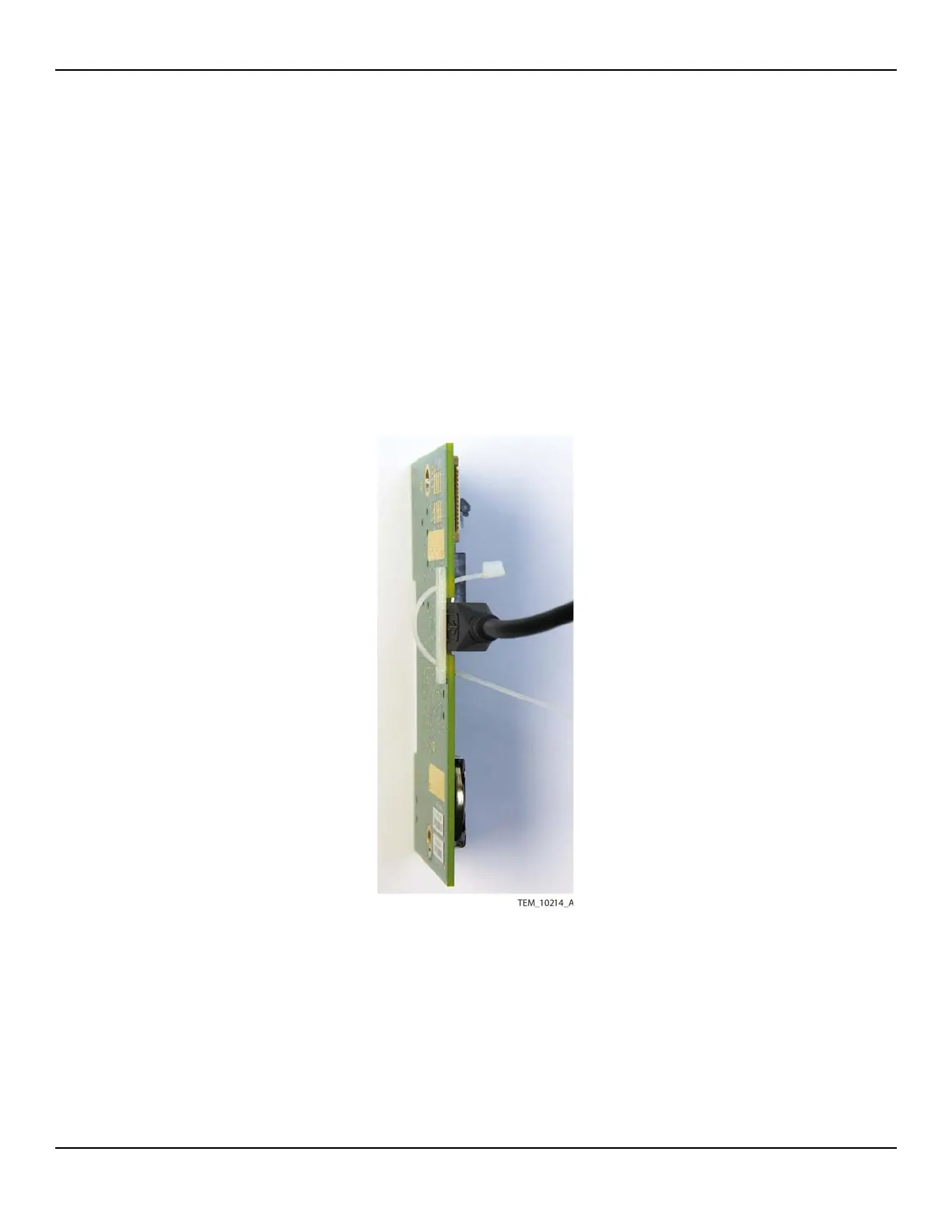
6. Attach the USB cable to the new UI PCBA as follows (Figure 10-13):
a. Place the backing plate against the non-component side of the PCBA, cover-
ing the notch at the top of the board. Align the holes in the backing plate with
the holes on each side of the notch.
b. From the front of the PCBA, insert the cable tie into either hole and through
the backing plate.
c. From the back of the PCBA, insert the cable tie through the opposite hole in
the backing plate to the front of the PCBA.
d. Connect the USB cable to the J203 connector.
Figure10-13.Attaching Backing Plate and Cable Tie to UI PCBA
e. Adjust the cable tie so that the lock is snug against the PCBA.
f. Secure the USB cable by pulling the cable tie through the lock until the tie is
snug against the connector.
g. Trim off the end of the cable tie.