Internal Component Replacement (Inside Rear Enclosure)
11-16 Service Manual
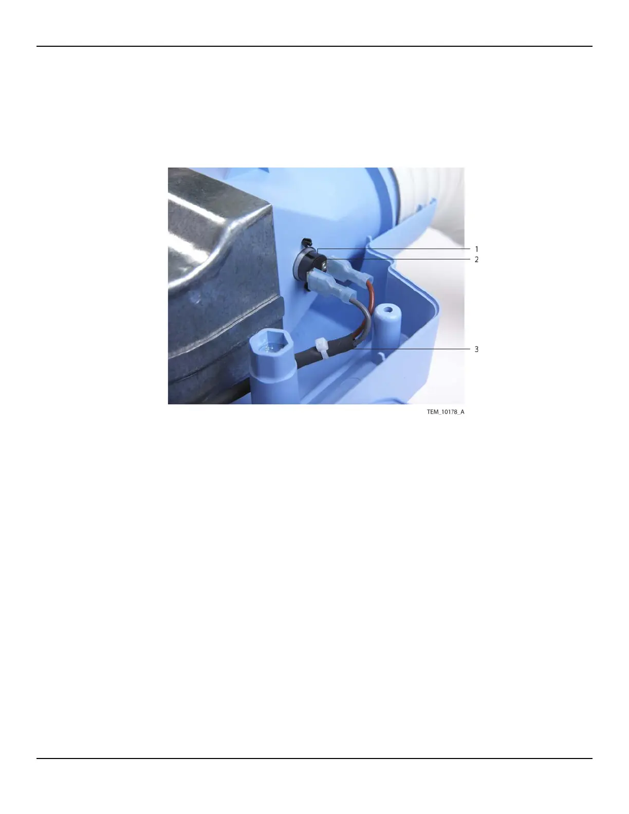
4. Disconnect the thermostat cable from the two terminals on the thermostat
(Figure 11-15).
Figure11-15.Thermostat Cable Connection to Thermostat
5. Connect the new thermostat cable to the two terminals. Note that the wires can
be connected to either terminal, but for consistency across units they should be
connected as shown in Figure 11-15.
6. Connect the other end of the thermostat cable to the 2-pin P113 connector on
the Power PCBA. Make sure that the connector is oriented as shown in Figure 11-
14 on page 11-15, and that it is fully seated.
7. Make sure that thermostat cable is routed as shown in Figure 11-13 on
page 11-14. It must be positioned to the inside of the adjacent screw boss and
pole clamp mounting bolt and inside the tabs around the fan assembly.
1 Thermostat 3 Thermostat Cable
2 Terminal (x2)