Internal Component Replacement (Inside Front Enclosure)
10-24 Service Manual
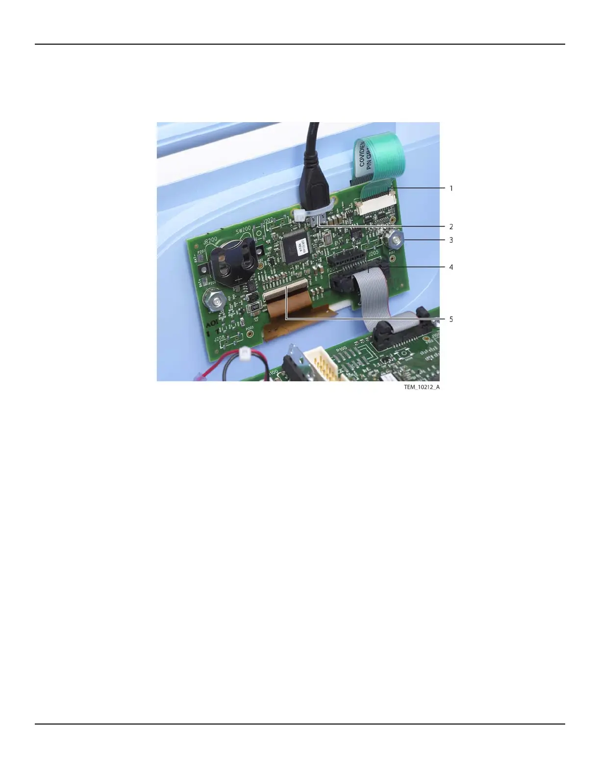
Figure10-19.UI PCBA Connections
5. Remove the UI PCBA from its mounting screws as follows:
a. Remove the nut from each mounting screw.
b. Remove the lock washer from each mounting screw.
c. Slide the UI PCBA and shoulder washers off the mounting screws (USB cable
still attached). Leave the shoulder washers in the mounting holes on the
PCBA.
d. Leave the nylon spacer on each mounting screw.
1 Keypad Cable
(J204 Connection)
4 Ribbon Cable
(P204 Connection)
2 USB Cable
(J203 Connection)
5 Display Cable
(J207 Connection)
3 Nut, Lock Washer, Shoulder
Washer (x2)